

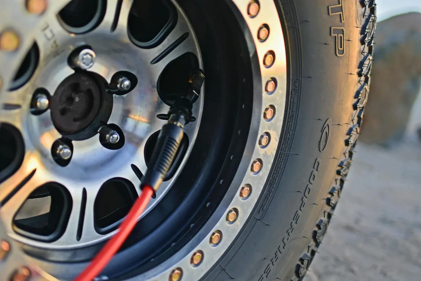
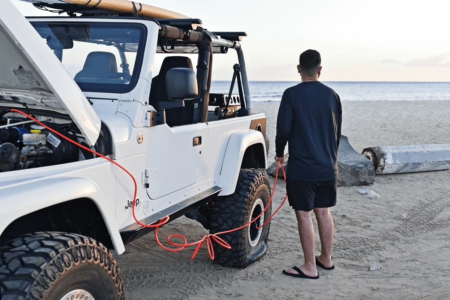
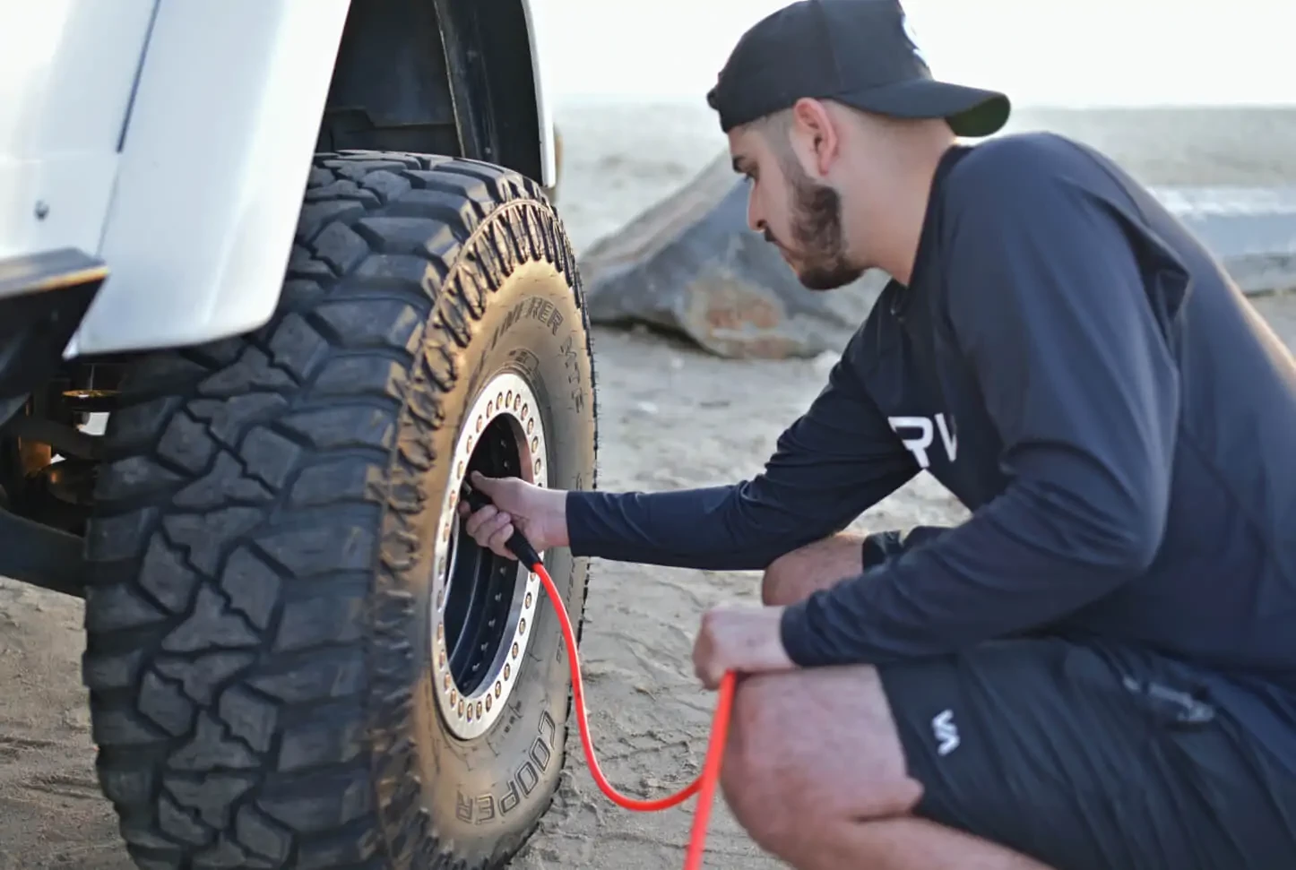
Ask an off-roader, “Which accessories on your build are the most useful?” and you’ll get a handful of different responses – but on-board air will make the list every time. ARB air compressors not only power Air Lockers, but also make airing up tires a breeze after a long day on the trail. They can be used to blow out dusty or sandy interiors. What’s even better? This invaluable adventure upgrade is easy to install with different mounting location options and brackets.

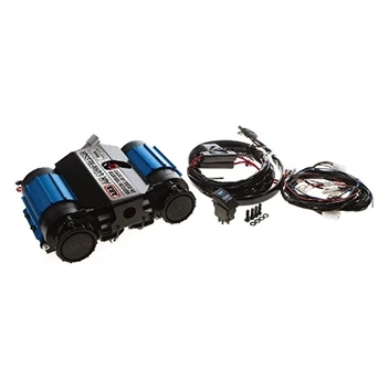
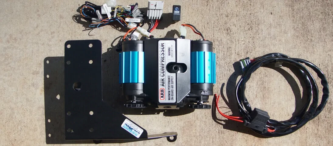
PARTS
TOOLS & ACCESSORIES
- Basic mechanics tool set
- Wire cutters, stripers, and crimpers
- Multimeter
- Heat Gun
- Thread Sealant
- Soldering Iron
- Electrical Tape or Heat Shrink
- Cable ties
INSTALLATION
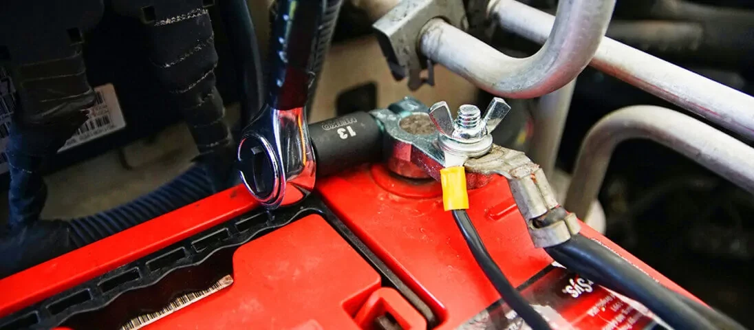
- Disconnect the starting battery.
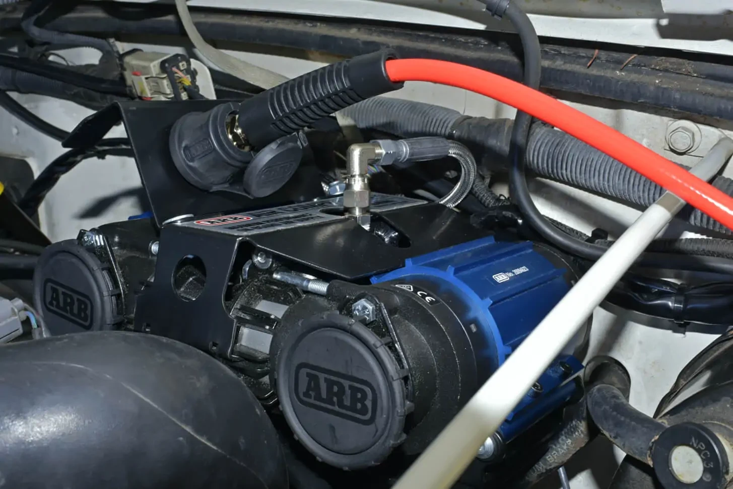
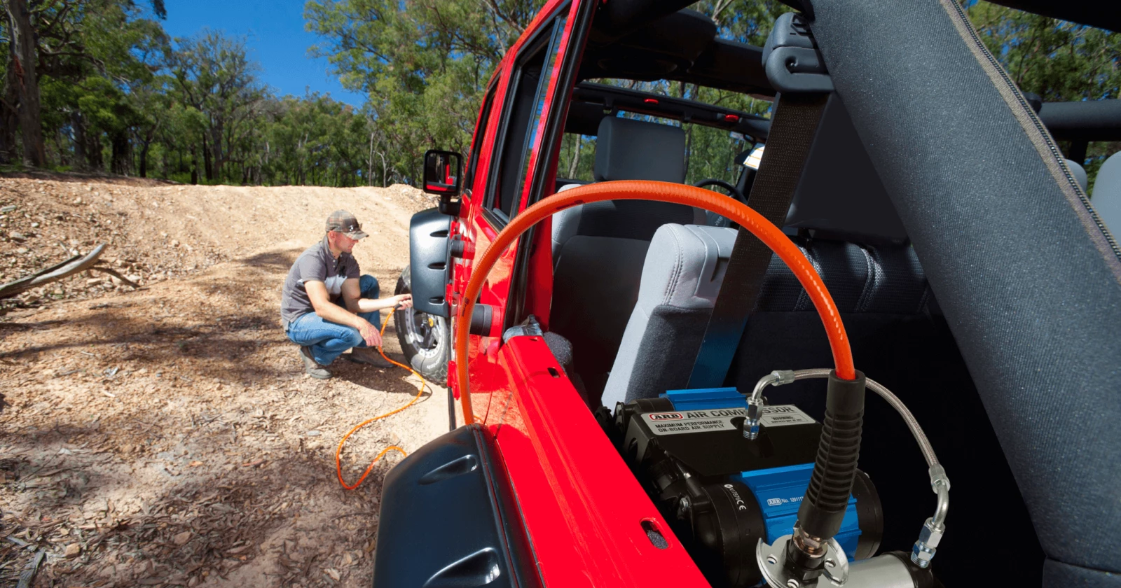
- Find a suitable location for the ARB Air Compressor. Each ARB Air Compressor has a built-in mounting bracket; however, vehicle specific brackets can also be used to make the installation easier.
- Using the built-in bracket? Use the provided template to mark and drill holes in the desired location.
- Attach the compressor with the provided hardware.
Using a vehicle specific bracket? Attach the compressor to the bracket then to the vehicle by following the provided instructions.
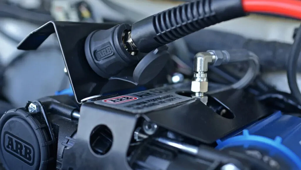
A hose coupling should not be installed directly onto the compressor if it is being used for tire inflation. Instead, use the ARB Manifold or a remote coupling setup.
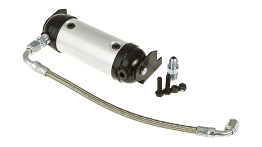
MANIFOLD
The ARB Compressor Manifold is not only required for Air Lockers but also for inflation.
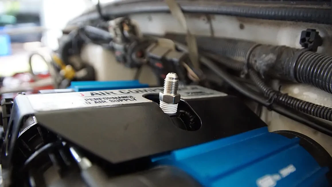
- Apply thread sealant to both of the ¼” fittings. Thread one into the compressor and the other into the manifold using a 14mm socket.
- Apply thread sealant to the threads of the hose coupling. Thread it into the large port on the manifold.
- Find a suitable mounting location for the ARB Manifold, no more than 9 inches away. ARB and some aftermarket vehicle brackets will have an integrated manifold mount.
- Connect the stainless-steel braided air hose to the compressor and manifold using a 14mm wrench.
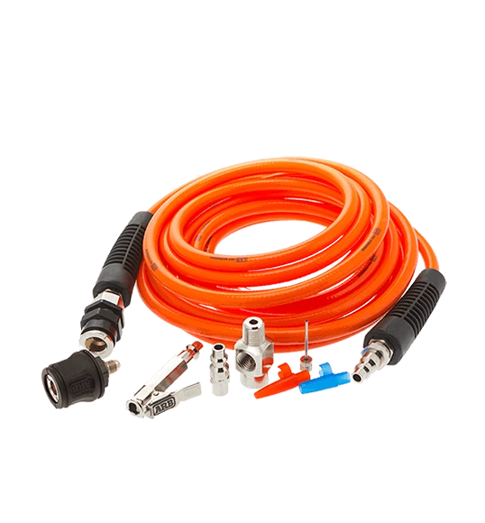
REMOTE COUPLING
Fittings vary upon application and setup. Explore air systems accessories >>
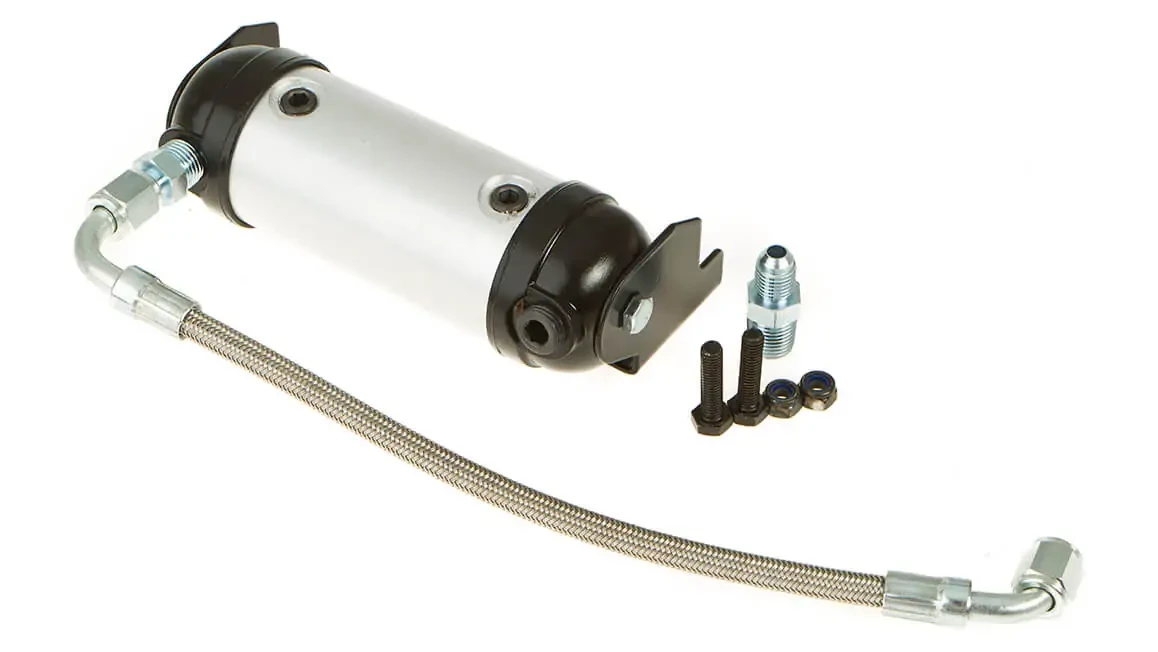
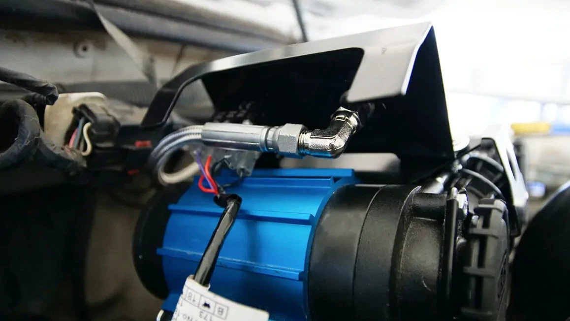
Various hoses and fittings are used to create a remote coupling that suits this setup. We will be using the following parts for this install: hose coupling (0740111), coupling dust cap (0740113), 1M hose (0740203), ¼”-JIC4 Adapter (0740101), and JIC4 Elbow (0740104).
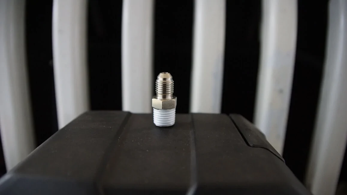
- Apply thread sealant to all ¼” fittings. JIC-4 fittings will not require thread sealant since they are flared.
2. Use a 14mm socket to thread the fitting (ARB #0740101) into the compressor. Do not overtighten.
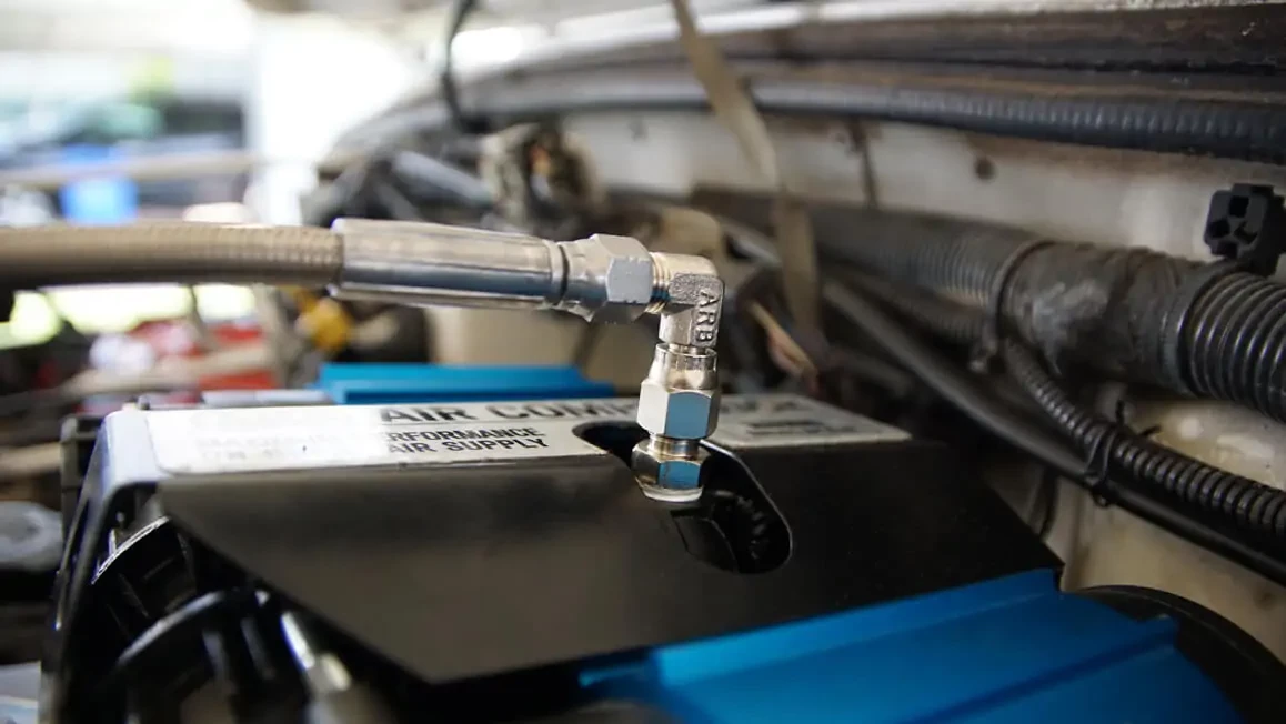
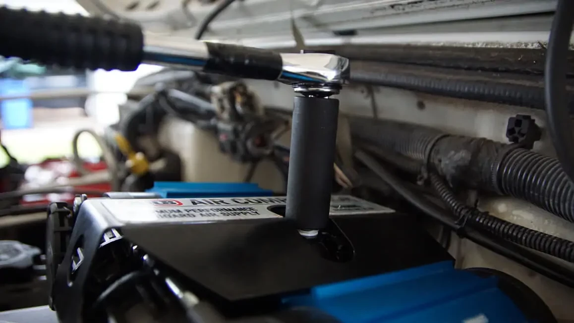
3. To prevent kinks in the reinforced hose, use 90-degree fittings (ARB #0740104). Attach the ARB reinforced hose (0740201).
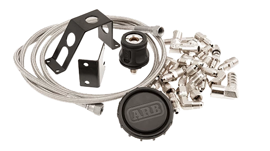
4. Find a location for the hose coupling (ARB #0740111). Remote Hose Coupling Kit #171314 will include a bracket. However, the JIC-4 hose coupling is a surface-mounted hose coupling. Simply drill a 7/16” hole, place the coupling into the hole, and thread the backing nut to secure it in place.
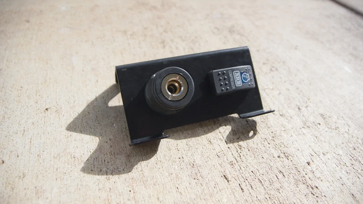
For this installation, a custom hose coupling and switch bracket will be used. A similar option is #3501050.
5. Use a 14mm wrench to connect the reinforced hose to the hose coupling.
WIRING
1. Disconnect the negative terminal from the battery.
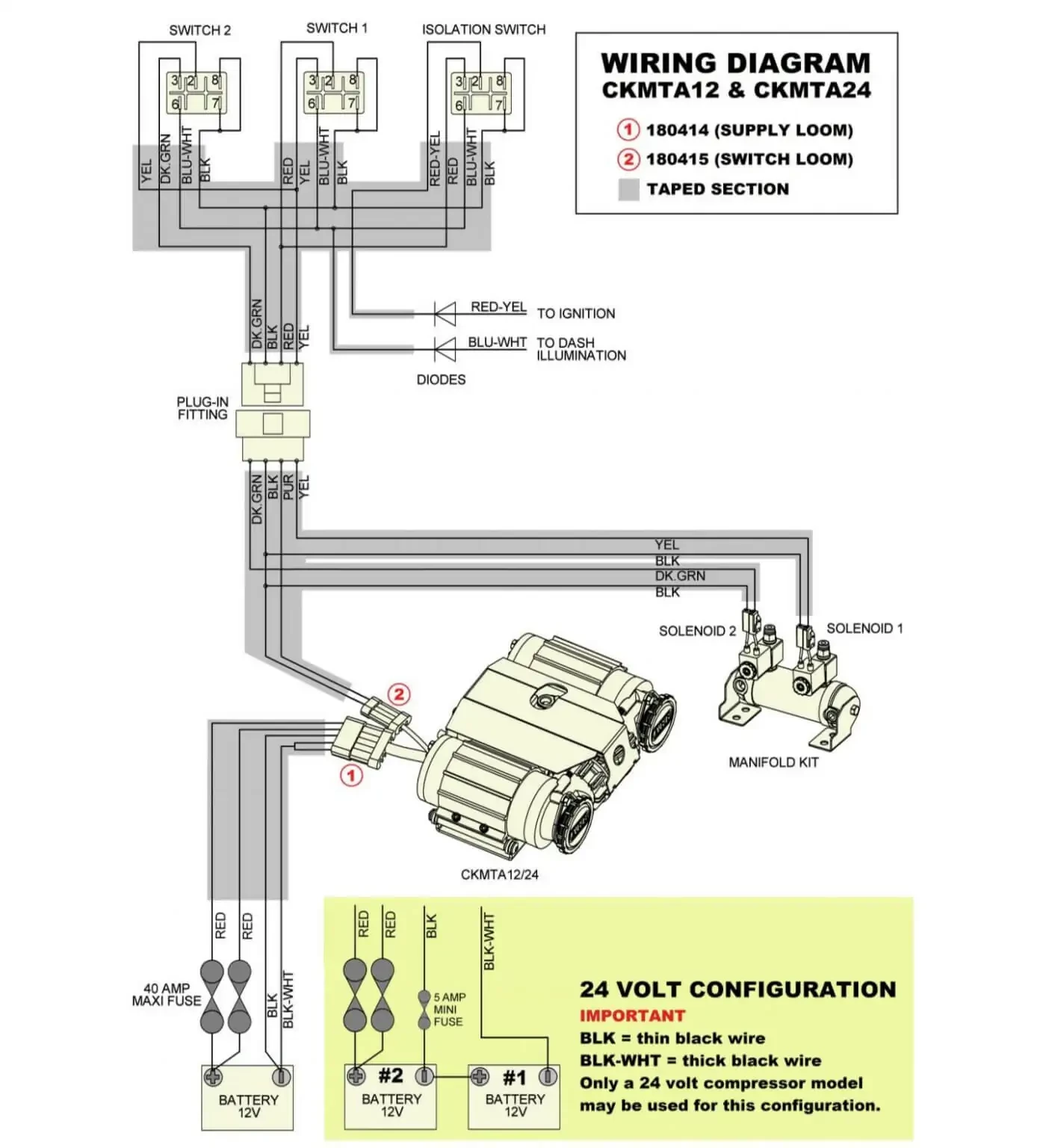
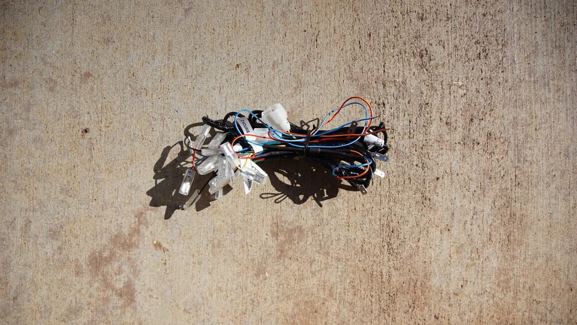
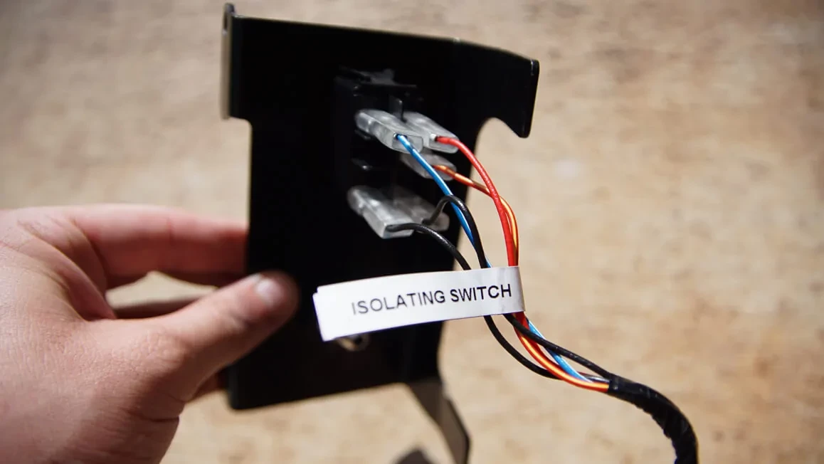
SWITCH LOOM (180415)
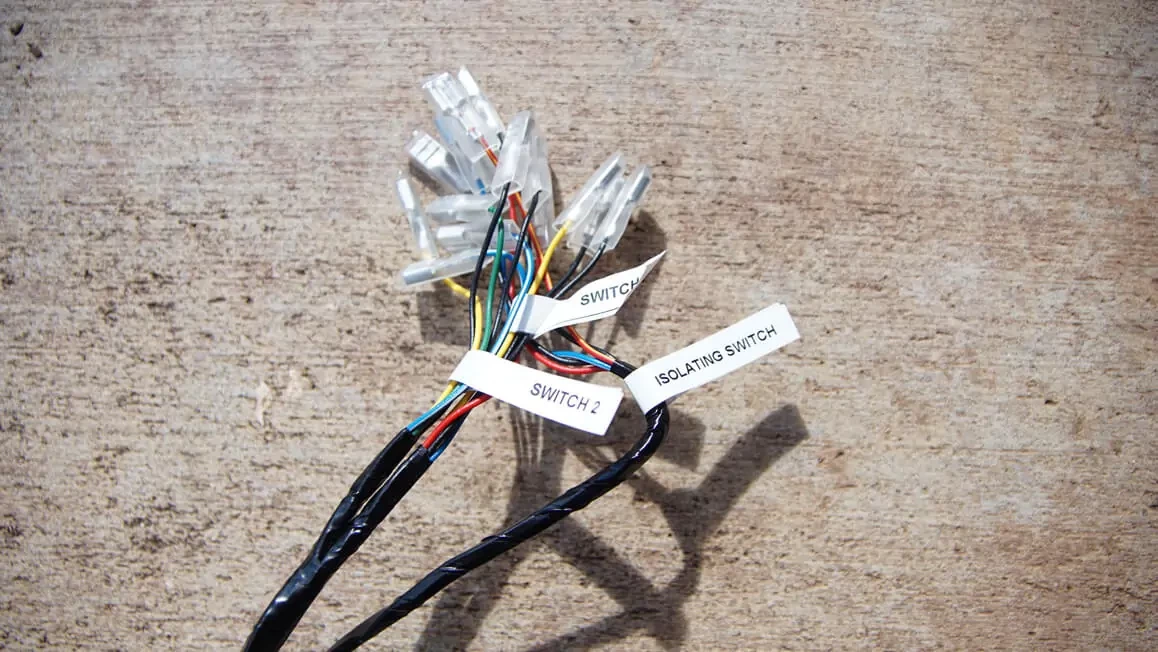
This harness will be separated by three sections:
Isolation: On/Off
Switch 1: Rear locker (or front locker if no rear locker is installed)
Switch 2: Front locker
NOTE – For safety reasons, the front locker can only be actuated when the rear locker switch is engaged.
If Air Lockers are not installed, Switch 1 and 2 can be left disconnected.
If Air Lockers are installed, or the Compressor switch is desired in the cab, feed the switch harness through an existing grommet in the firewall.
- Find an adequate mounting location for the switch(es) then pin them per included wiring diagram.
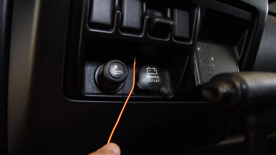
2. Locate an ignition/ACC power circuit, minimum 8 amps, using a multimeter. This circuit must only be live when the vehicle ignition key is in either the ‘ACC’ position or in the ‘ON’ position. Connect the red/yellow wire to this circuit using a method of your choice.
NOTE – This is not an optional step. The compressor will not power on if this step is not performed.
HINT – Cigarette lighter or fuse box may be an adequate source.

3. Locate an illumination circuit (a circuit that powers on when the headlights are engaged) using a multimeter. Connect the blue/white wires to this circuit using a method of your choice.
NOTE – If shortening the red/yellow and/or blue/white wires, make sure not to remove the heat-shrinked inline diode that protects sensitive electronics from current leakage.
HINT – Low beam headlamp or fuse box may be an adequate source.
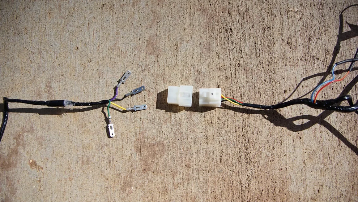
4. Route the 4 loose male spade terminals of the long section of the loom. This connection has been supplied disassembled to assist with routing through the firewall or any tight locations.
5. Assemble the 4 spade connectors into the supplied plastic connector housing. Each color should match; however, the red should connect to the purple. Plug the connectors together.

6. Route and connect the end of the switch loom to the compressor.
SUPPLY LOOM (180414)
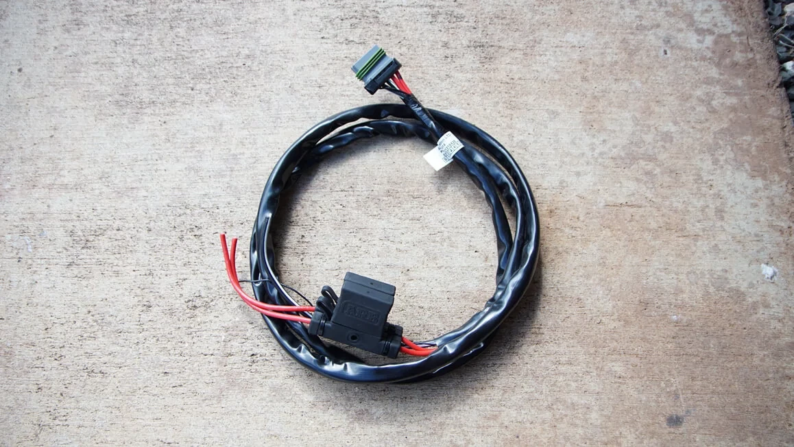
Depending on the compressor mounting location, it may be necessary to de-pin the connector in order to pass the harness through the firewall and/or extend the harness.
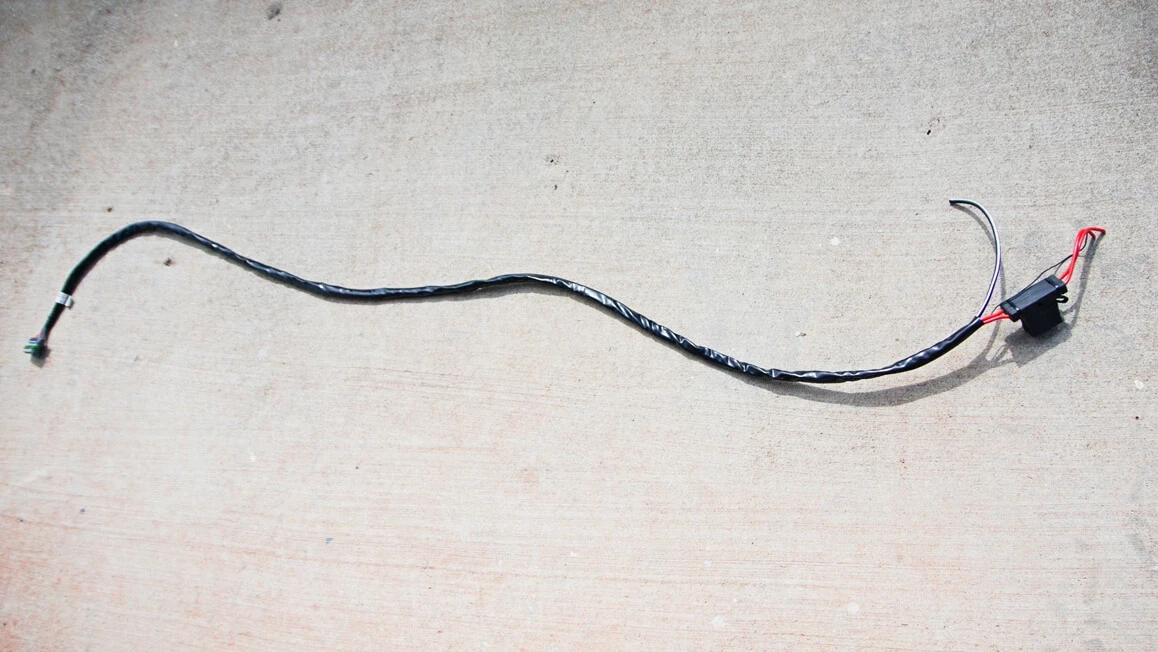
If the harness needs to be extended to reach the battery, ONLY use wire that is the same gauge or larger (+10AWG, -8AWG). ONLY extend the harness after the fuses. It is important that the fuses remain as close to the battery as possible.
Since this compressor is being installed under the hood, we will skip these steps.
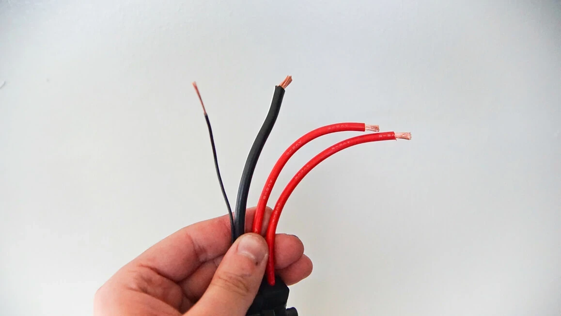
- Trim the excess wire at the battery if needed. Crimp 10-12AWG automotive ring terminals to each of the power leads. We will crimp the two ground wires to the same 6-8AWG automotive ring terminal.
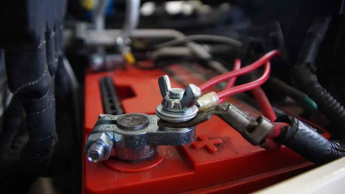
2. Connect both leads to the battery.
3. Secure all loom wiring with cable ties along its entire path.
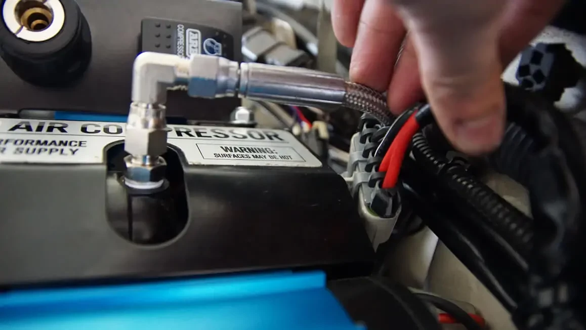
4. Connect the harness to the compressor.
LEAK TEST
- Power on the compressor and wait a few seconds until the system is fully charged.
- The compressor should not come on again for at least 15 minutes.
- If the compressor cycles, this indicates that a leak is present in the system.
- Spray a soap and water mixture on each of the fittings. Bubbles should appear at any leak points.

Up Next:
ARB Air Compressor Brackets
ARB Air Compressors are compact and universal; there is also a plethora of official ARB and aftermarket vehicle specific mounting …