

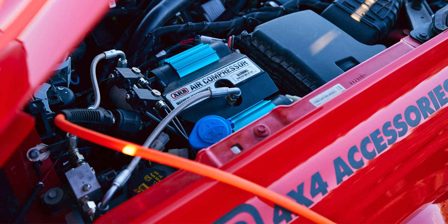
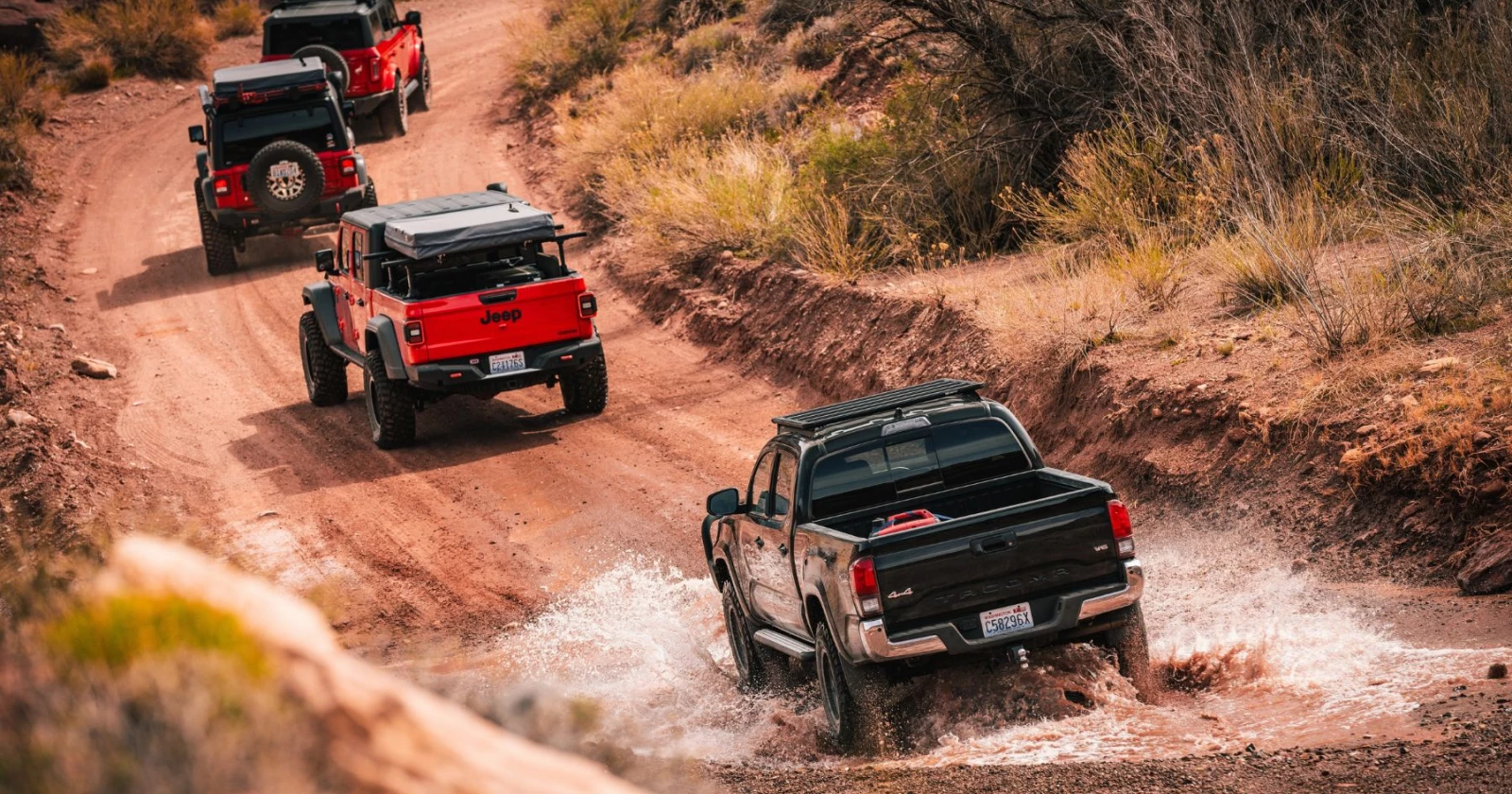
Whether you’re a seasoned overlander or a newbie off-roader – we can all reap the benefits of an onboard air compressor. Its many capabilities include actuating Air Lockers, inflating tires after deflating, setting tire beads, drying off cookware at camp, pumping up inflatable paddle boards and kayaks, and blowing the sand off your boots and floor mats.
What’s even better? This invaluable adventure upgrade can easily be installed under the hood of your Ford Bronco with our new mounting bracket that has been validated by Ford engineers. Follow along for step-by-step installation instructions.
Requires:
ARB Twin Compressor Mounting Bracket #3580030
ARB Twin Compressor #CKMTA12
ARB Manifold #171503
ARB Hose Coupling #0740112

1. Disconnect the negative battery terminal.
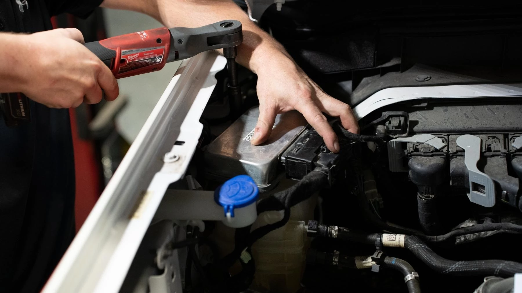
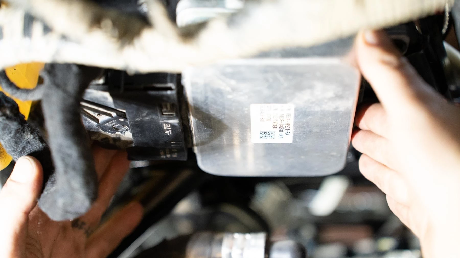
2. Unplug the DLCM and remove the two M6 bolts holding the mount to the body. DO NOT DROP.
3. Remove and discard the harness plug and earthing harness.
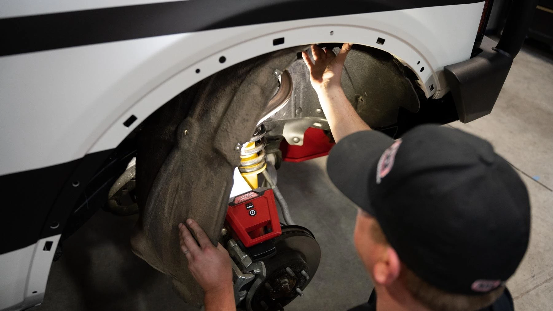
4. Remove fasteners (rear half only) for RHS inner guard and lower.
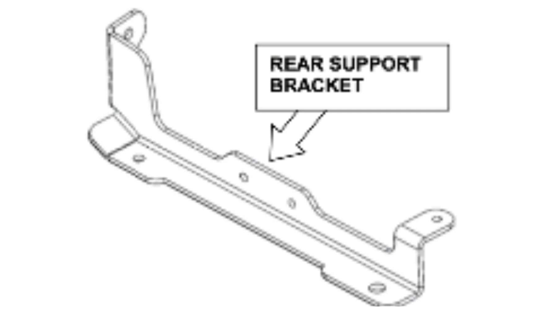
5. Fit the rear support bracket (4655173) using the factory OE M8 flange bolt. Leave loose at this stage.
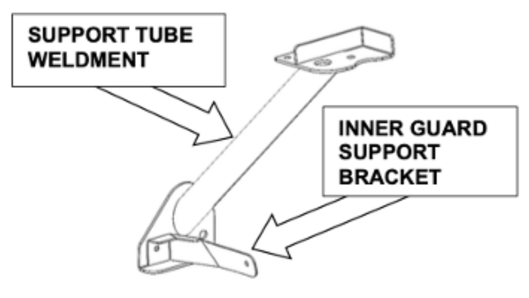
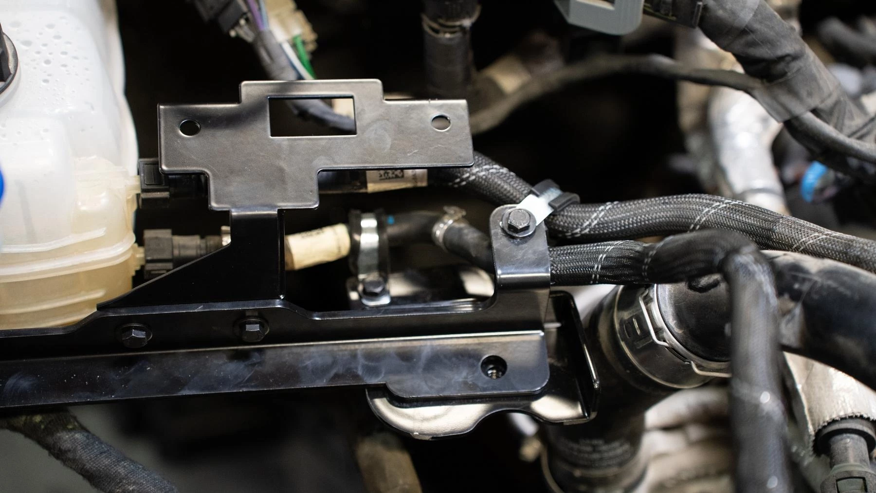
6. Feed support tube weldment to the firewall and locate it onto the M6 stud. Once on, place the inner guard support bracket over the same OE factory stud, and fasten the OE M6 nut. Torque: M6 – 7ft/lb
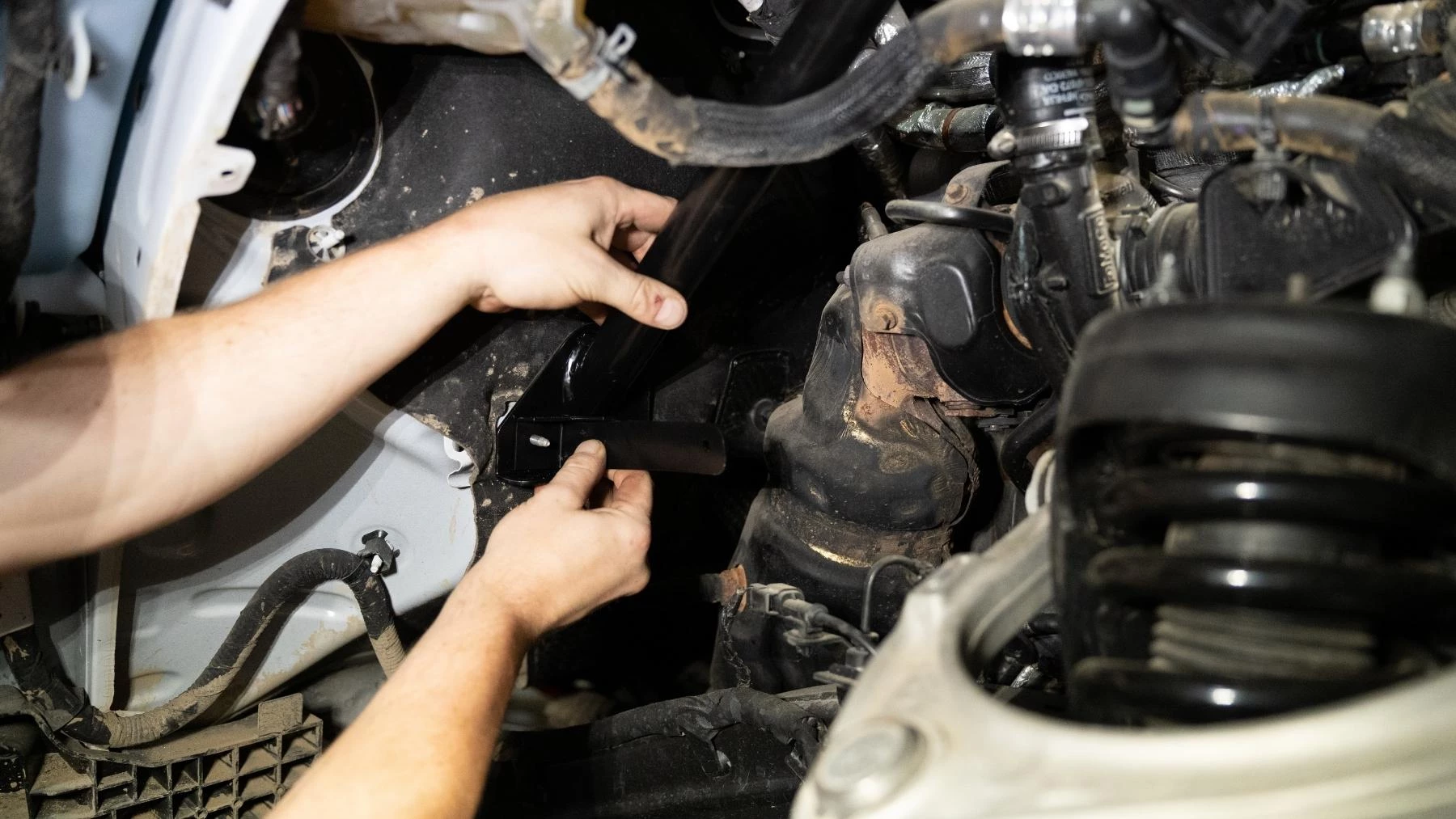
7. Use an M8 FL BOLT to temporarily brace the support tube to the rear support bracket.
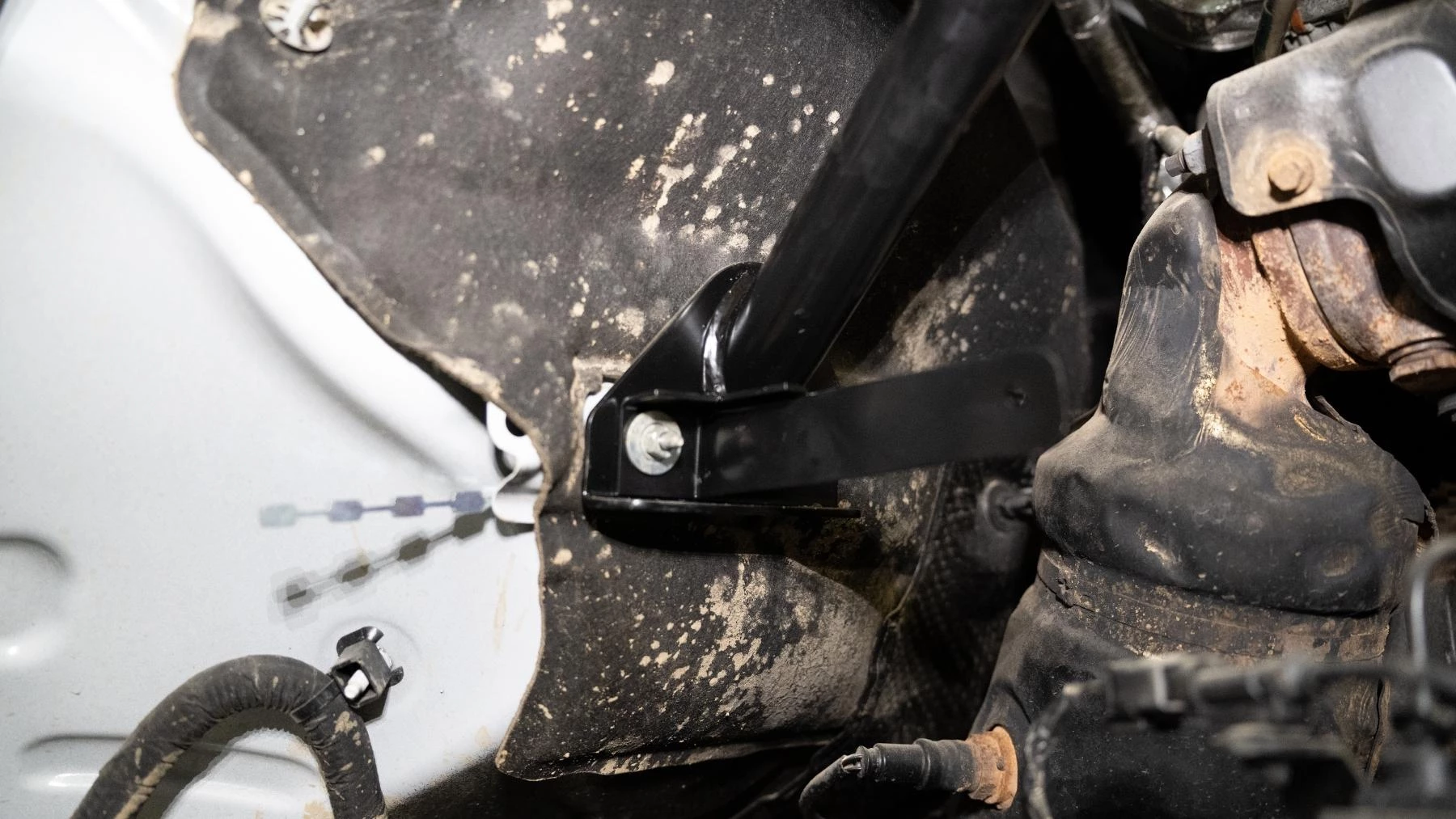
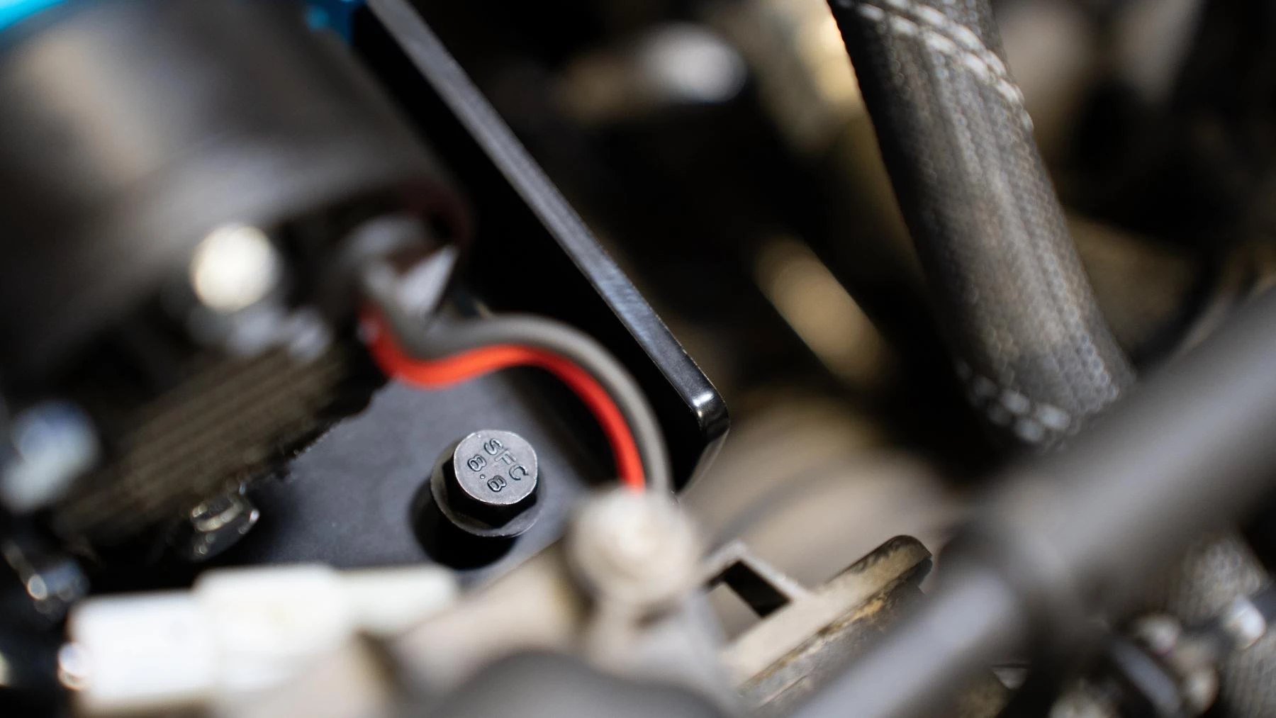
8. Fix the support arm to the firewall using the M10 Nut stick (bent profile shown below) and one M10 SEMS bolt. Torque: M10 – 32ft/lbs
9. Once the support arm is fixed, remove the M8 bolt from step 6.
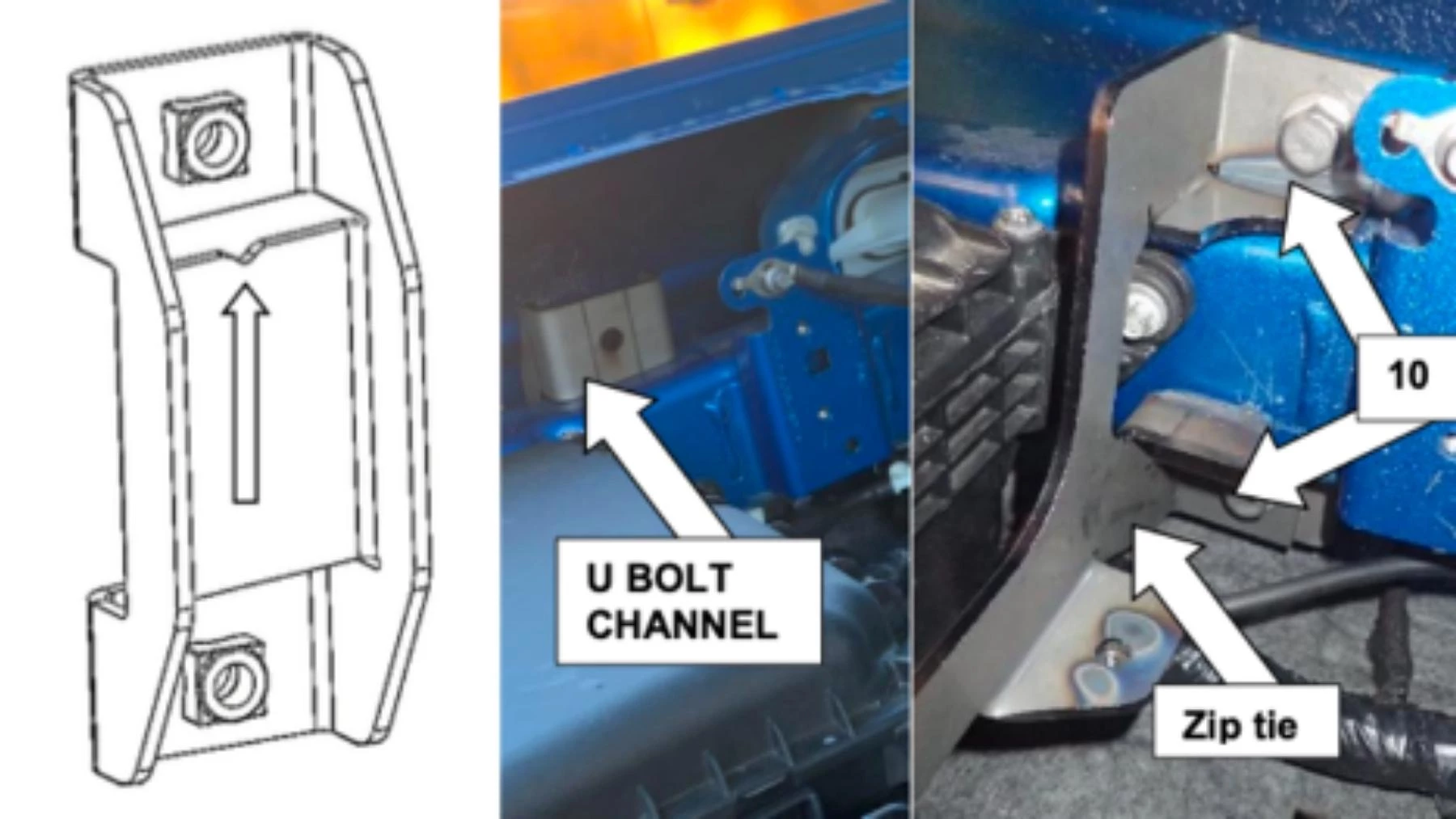
10. Feed the U BOLT CHANNEL behind the chassis from the top Note: the notch in the part faces toward the top.
11. Fasten the front support bracket to the U channel with two M10 FL bolts. Leave loose at this stage.
12. Support Wiring harness to mount with a Zip Tie.
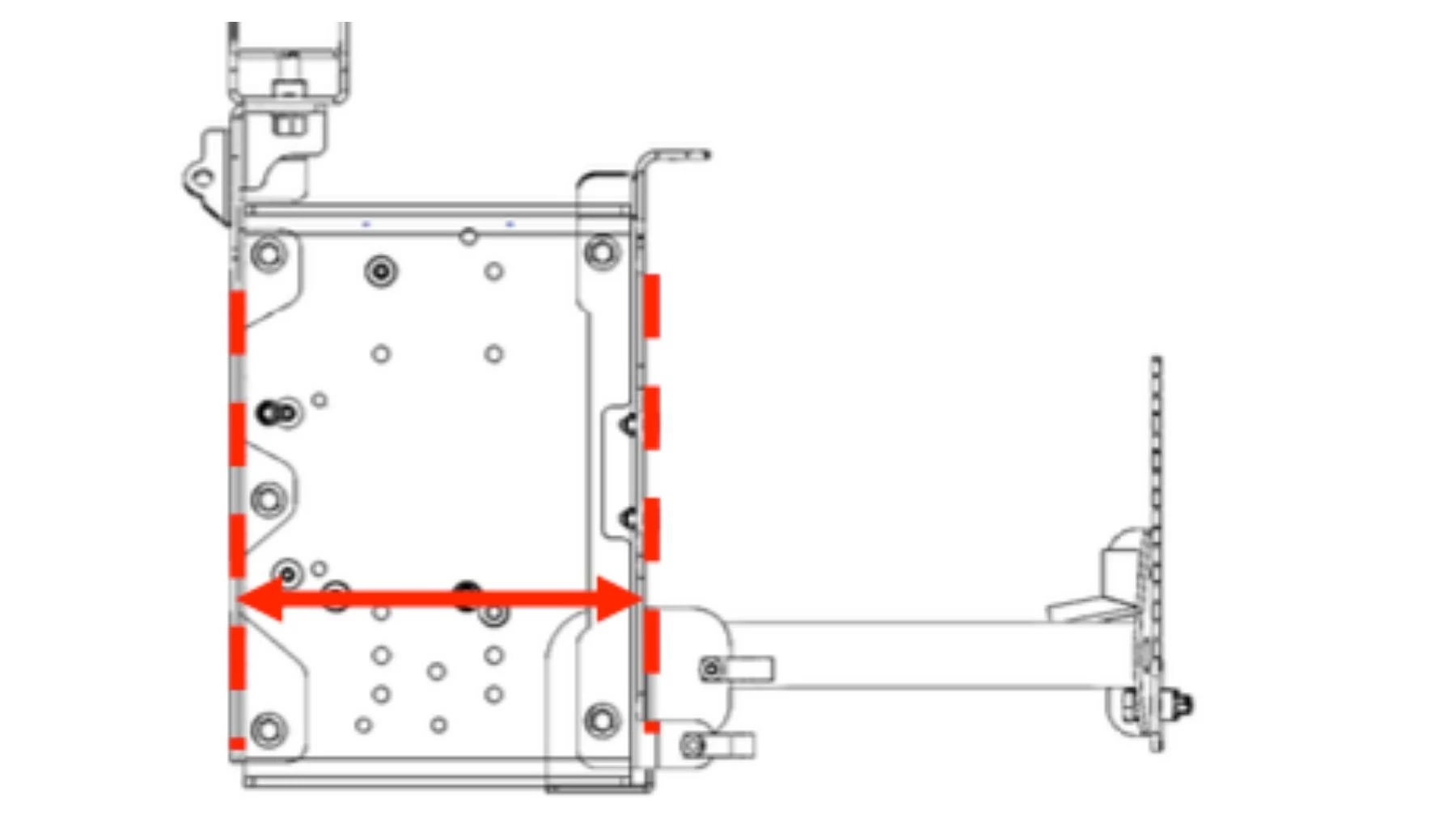
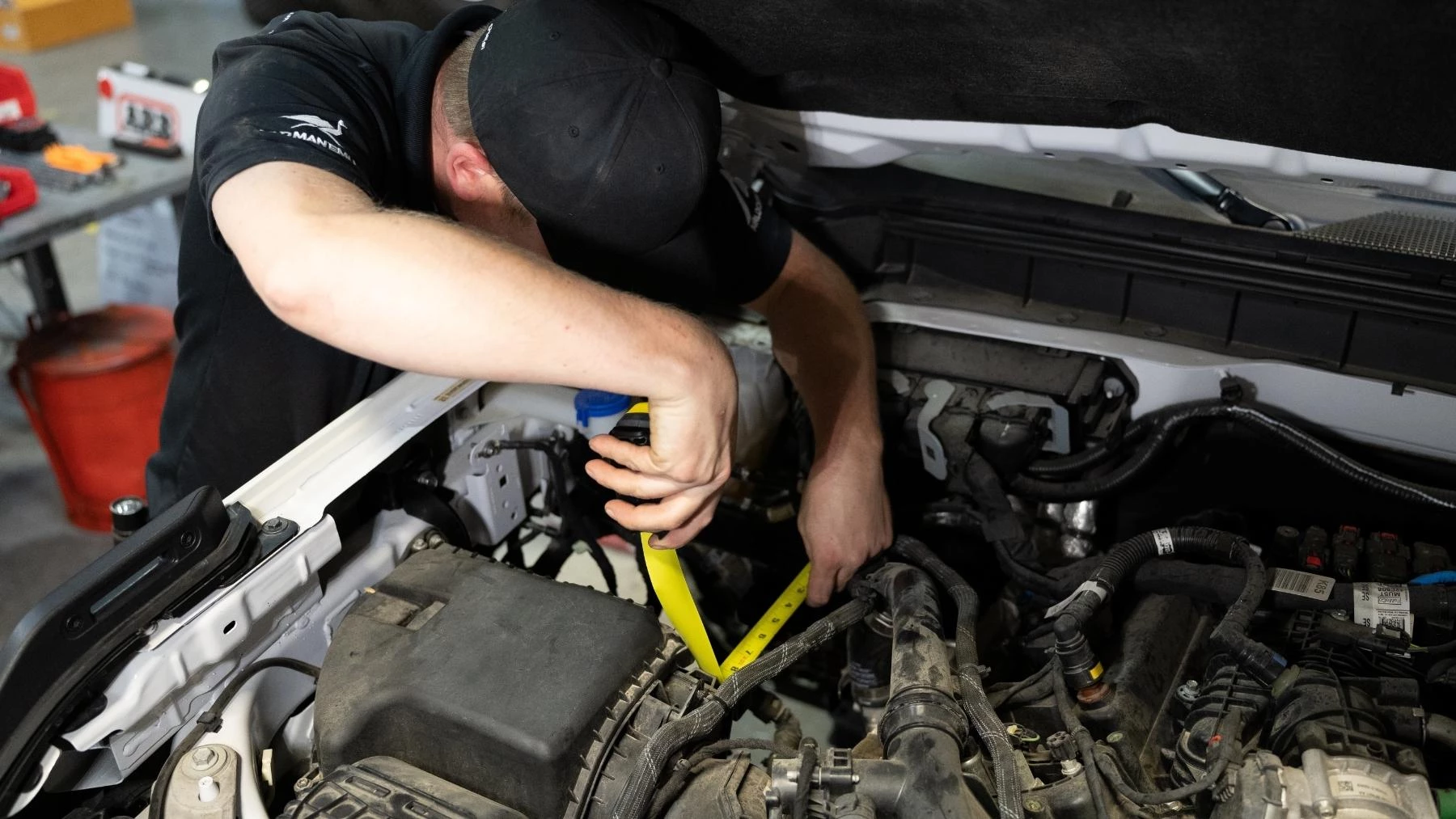
13. Measure outside to outside of the two support brackets. They Should measure 220mm (8.6”). If not, adjust accordingly.
14. Torque - M10 bolts to 32ft/lbs.
15. Torque OE M8 bolt from Step 4 to 16ft/lbs.
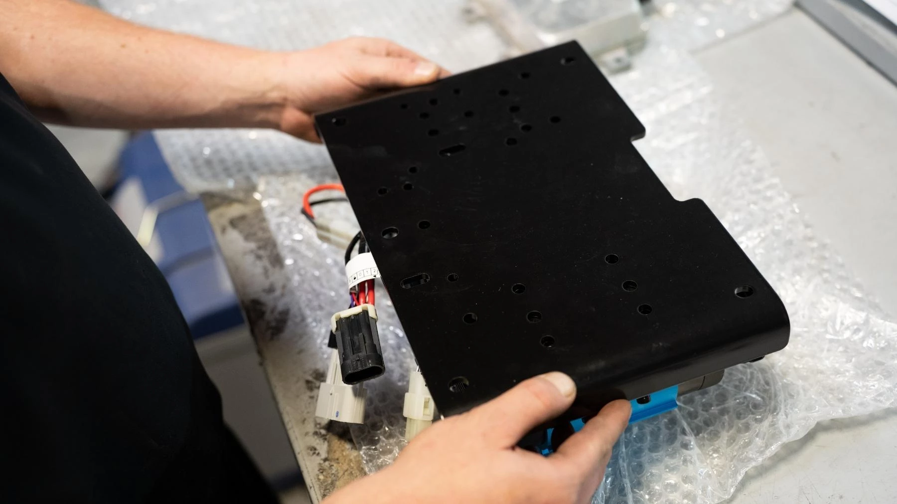
16. Remove Twin Compressor from the box and place it upside down on a soft surface.
17. Place the base plate onto the Compressor along with the DLCM.
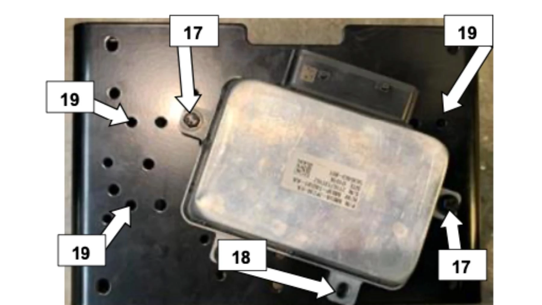
18. Using two M6 x 25 bolts, two M6 Flat washers attach the DLCM to the Compressor.
19. Use one M6 x 25, one M6 Flat washer, and one M6 FL nut on the third position of the DLCM.
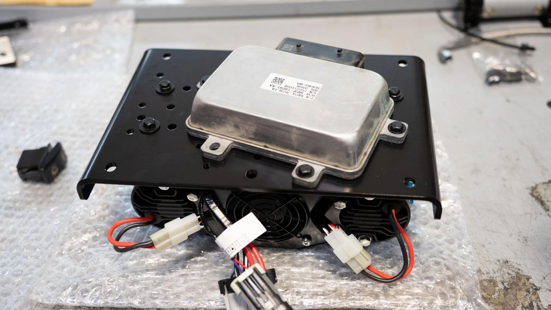
20. Use three fasteners supplied with the Compressor to complete the mounting, and torque to spec.
Torque: M6 – 7ft/lbs
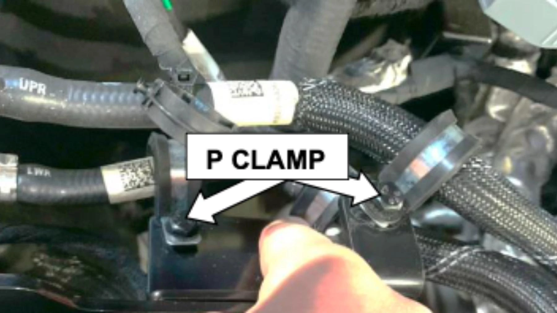
21. Secure the coolant hoses with two P clamps, M6x16mm bolts, washers, and flange nuts.
Torque: M6 – 7ft/lbs

22. Using 2 x M6 x 16 bolts, washers, and flange nuts, fit the Compressor Manifold bracket to the rear mount.
23. Fit the Manifold feet to the manifold mounting bracket using M6x16 bolts, washers, and flange nuts.
Torque: M6 – 7ft/lbs

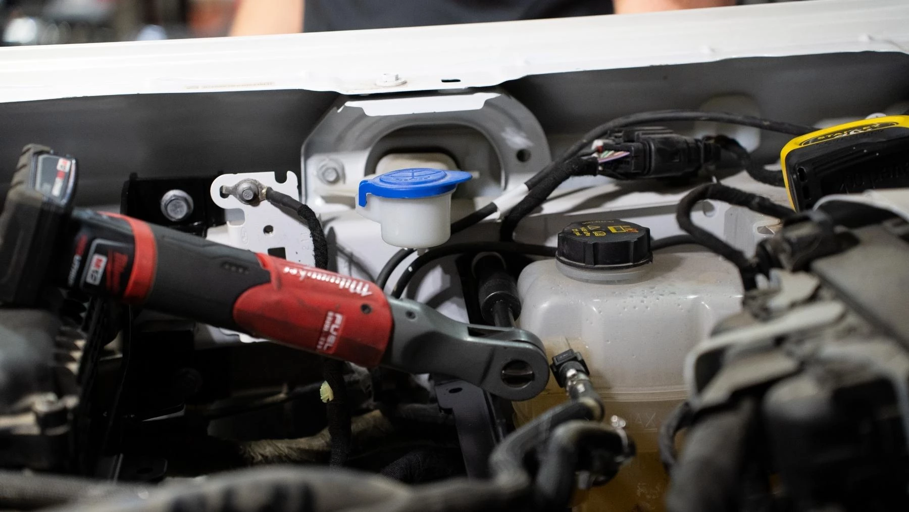
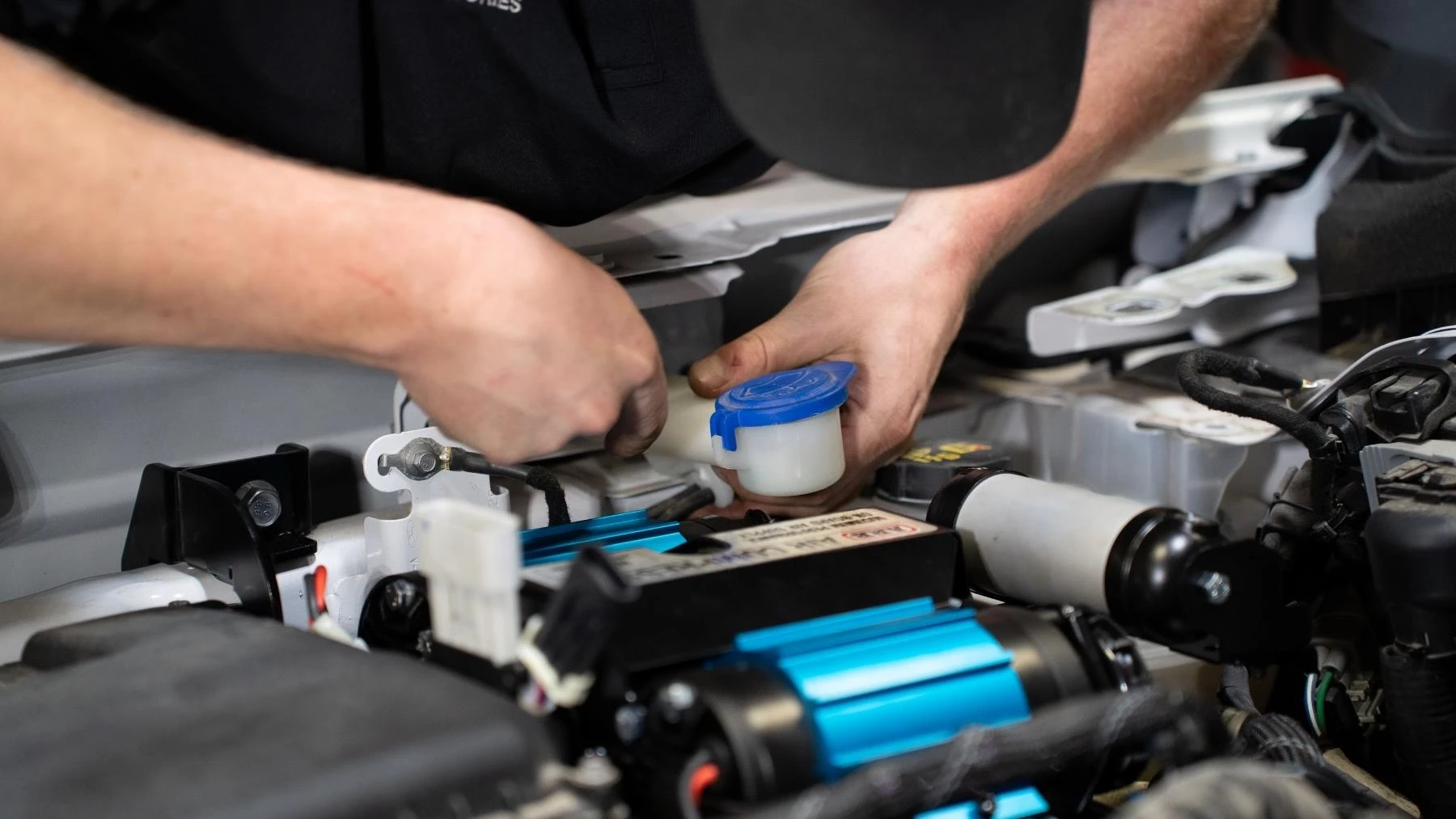
24. Temporarily remove the washer bottle filler neck by removing the bolts retaining them to the vehicle body.
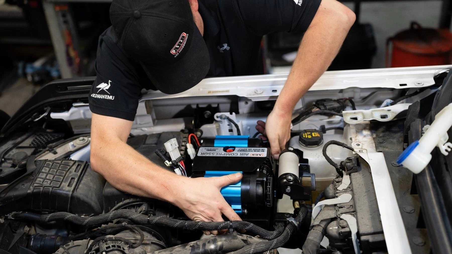
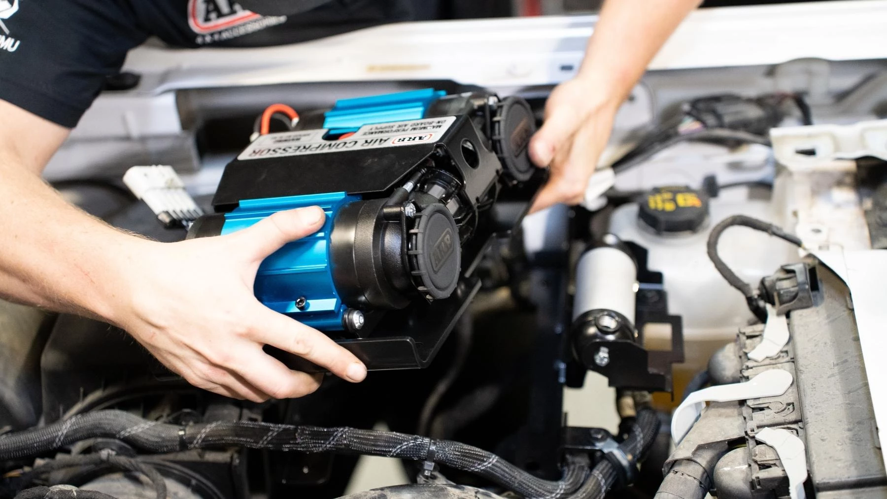
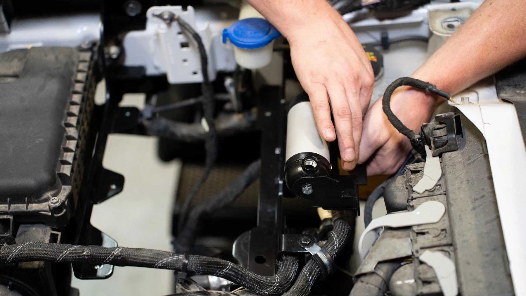
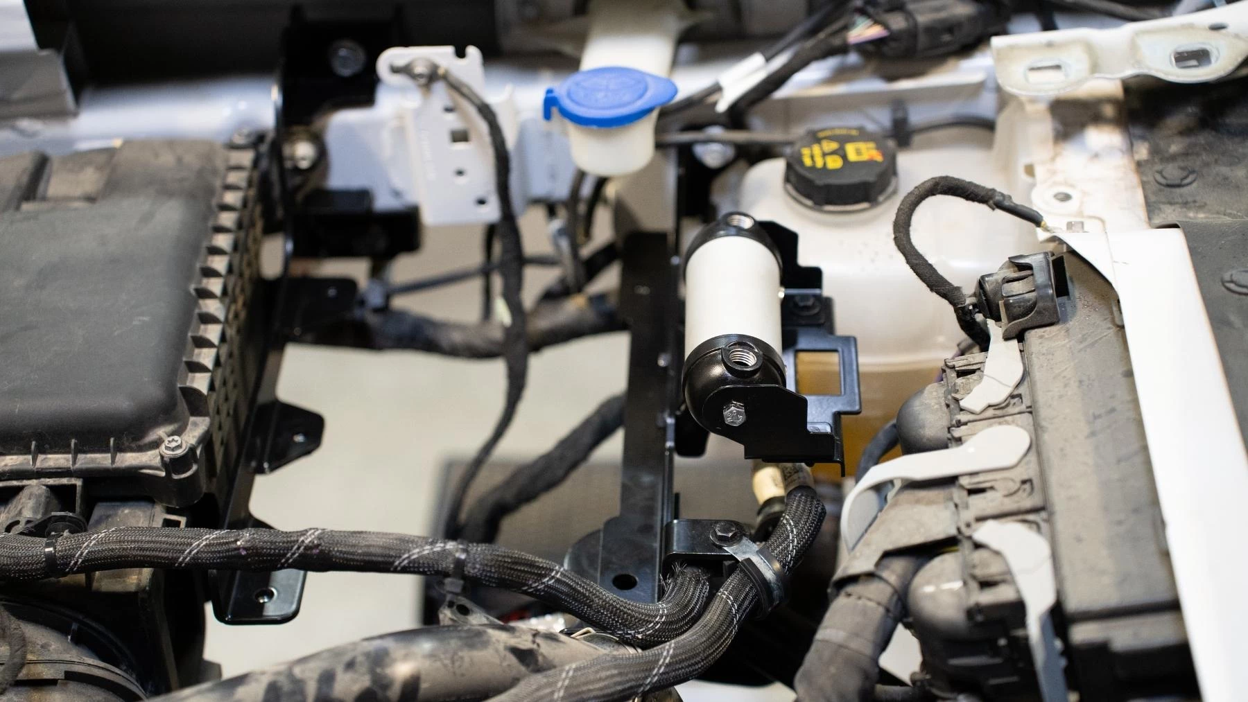
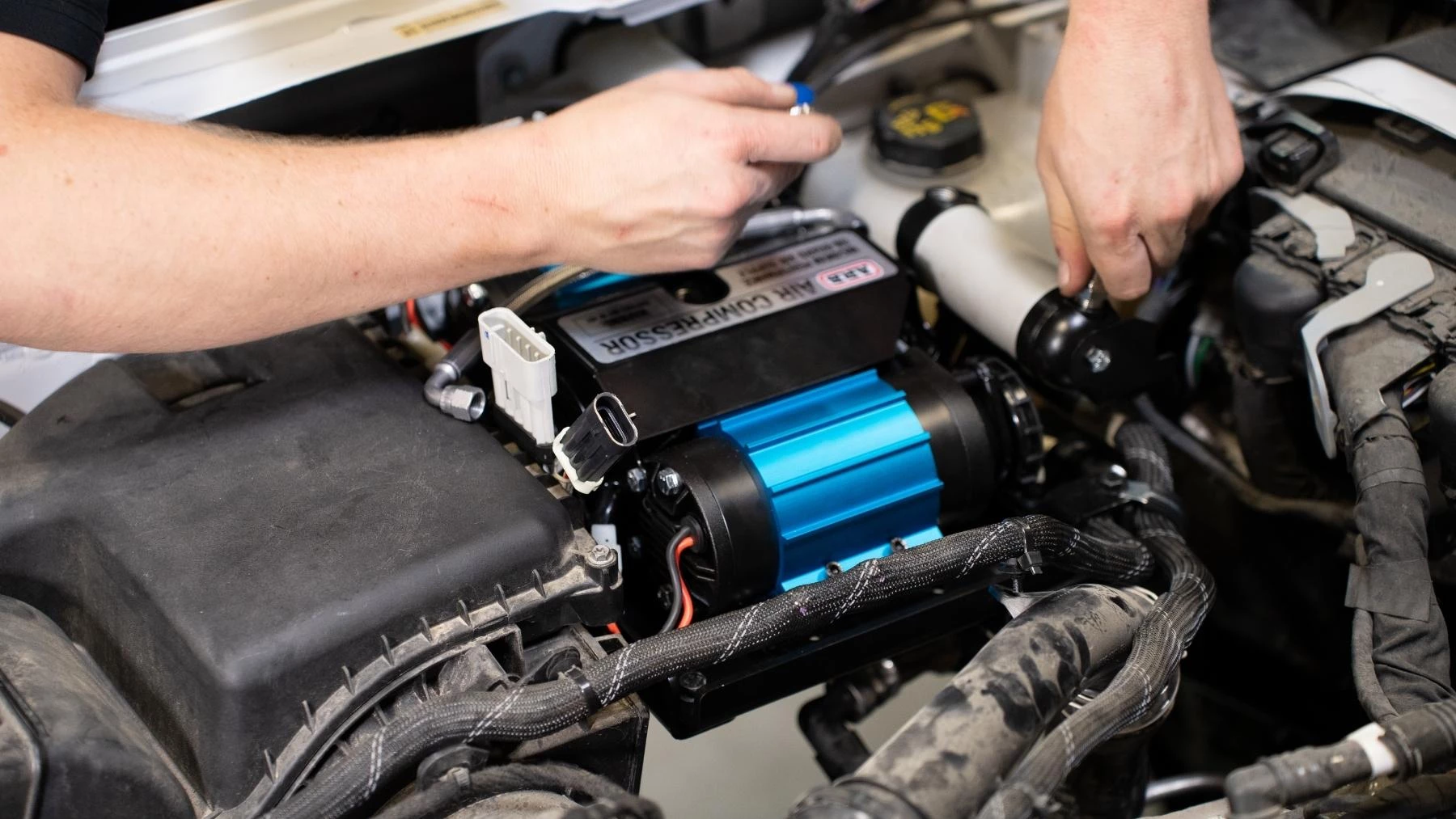
25. Carefully install the assembled Compressor, base plate, and DLCM onto the support brackets.
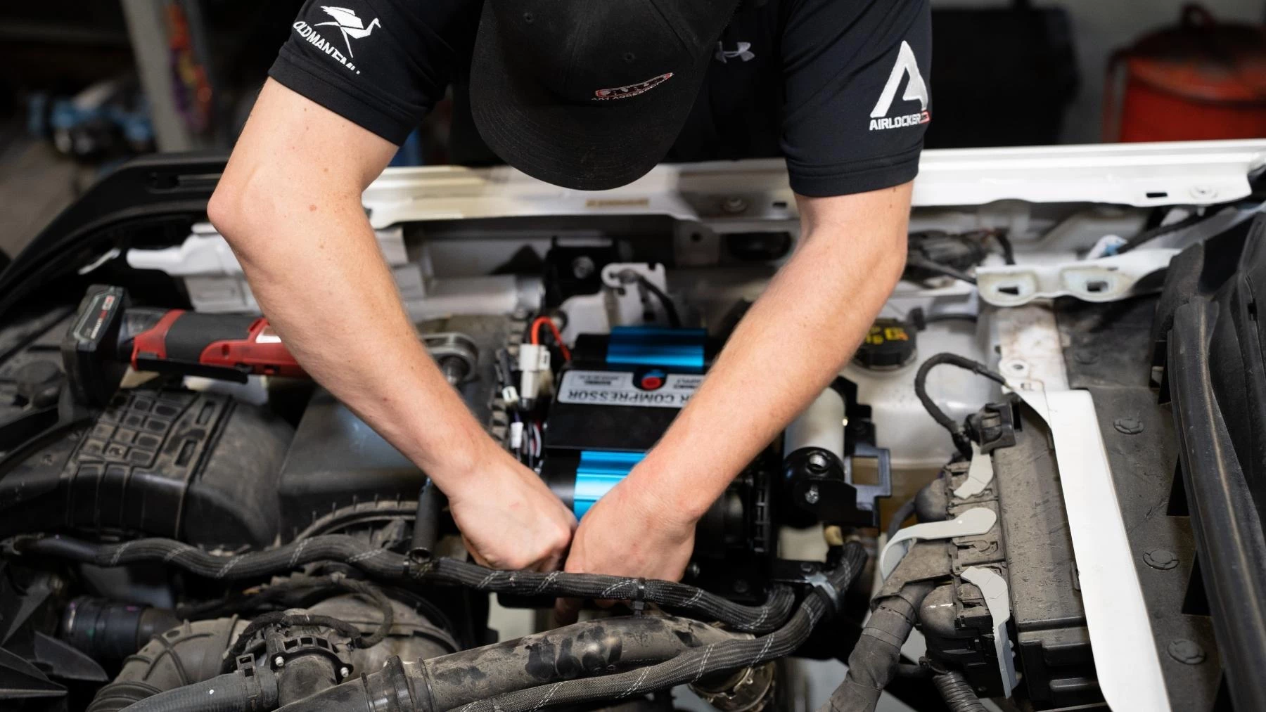
26. Use 5 x M8 FL BOLTS to secure the base mounting plate to the Front and Rear support brackets.
Torque: M8 - 16ft/lbs
27. Reinstall washer bottle filler neck 27. Plug in the DLCM by gaining access
28. Plug in the DLCM by gaining access through the inner guard.
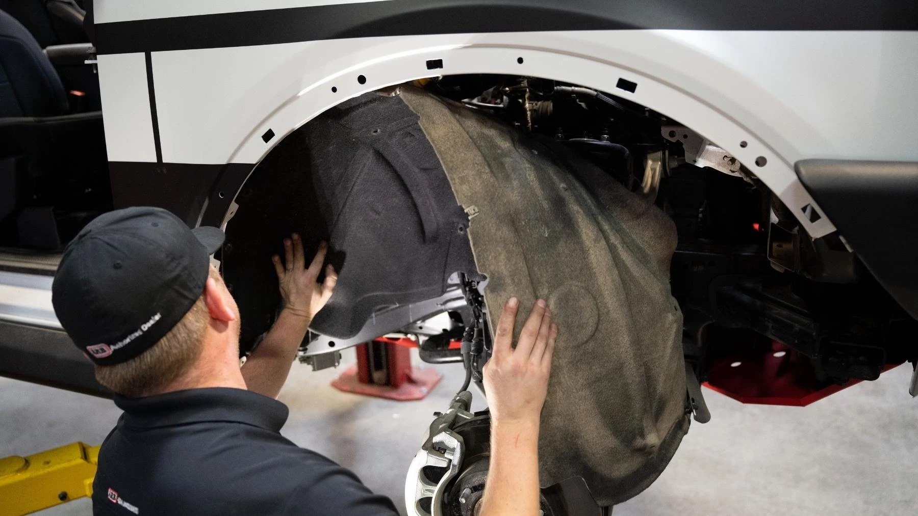
29. Reinstall the inner guard.
Note: Ensure to install the OE scrivet into ARB inner guard support bracket.
30. Using the fittings provided in kit 171503, fit 1 x JIC4 - 1/4 NPT fitting to the inboard manifold port (as shown in the image to the left).
Note: Ensure to use thread sealant on all 1/4 NPT threads.
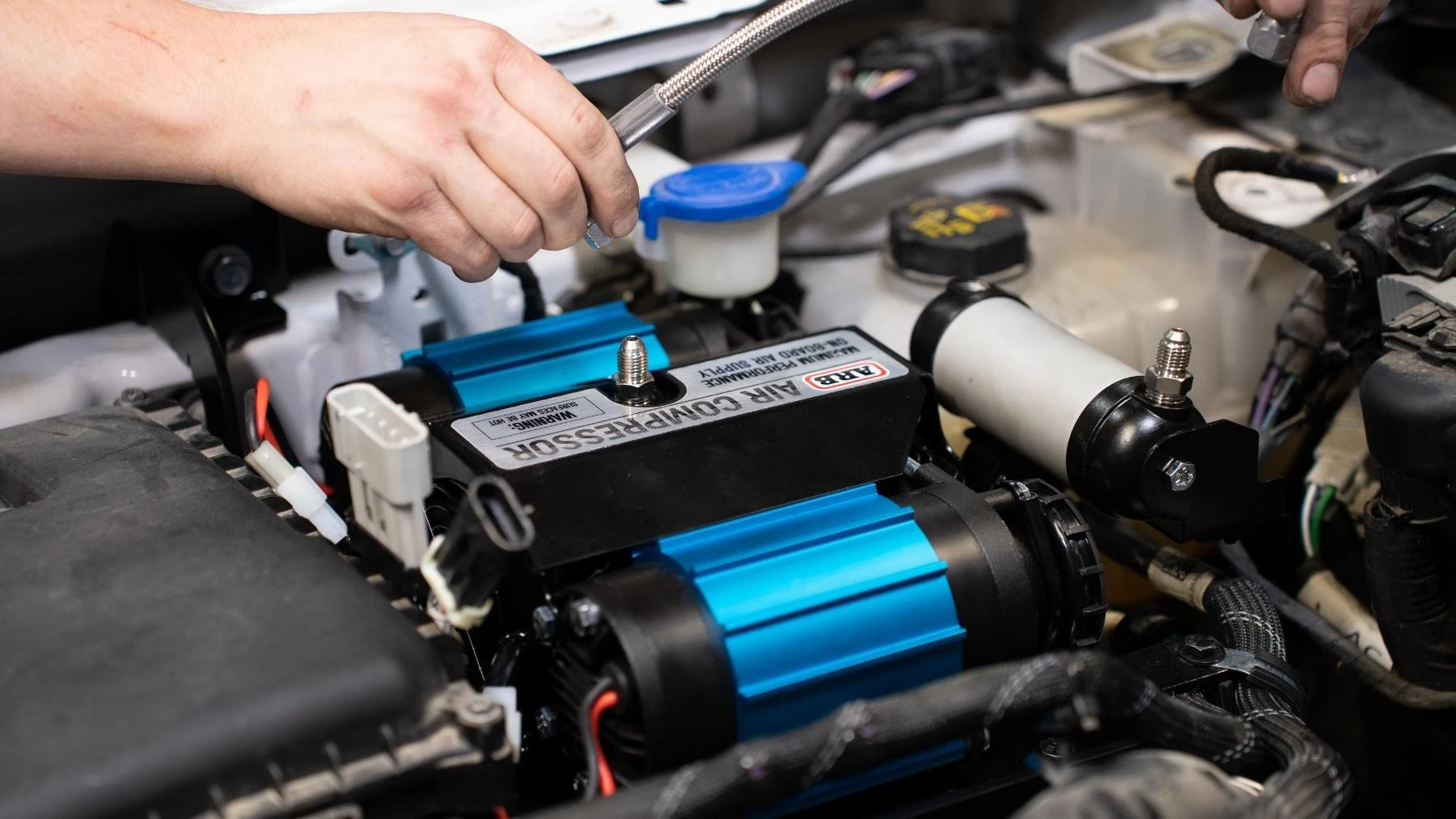
31. Repeat the same process for the compressor outlet port.
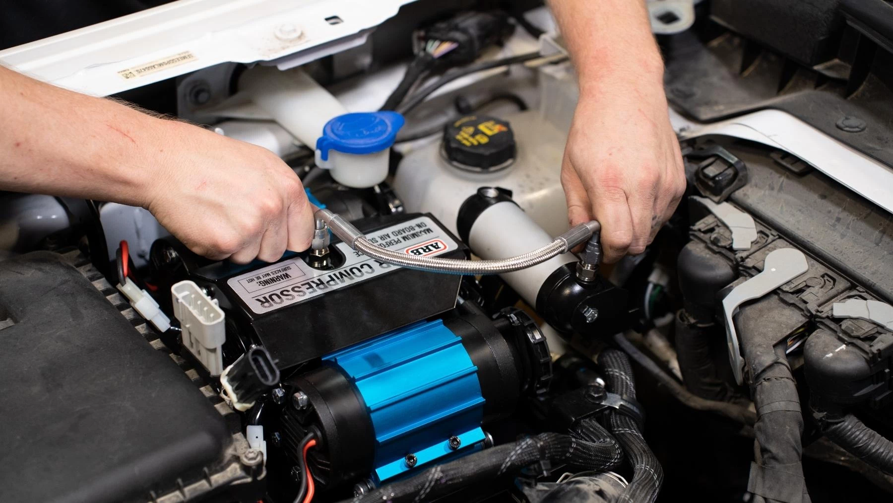
32. Connect the manifold to the compressor using the braided hose and tighten.
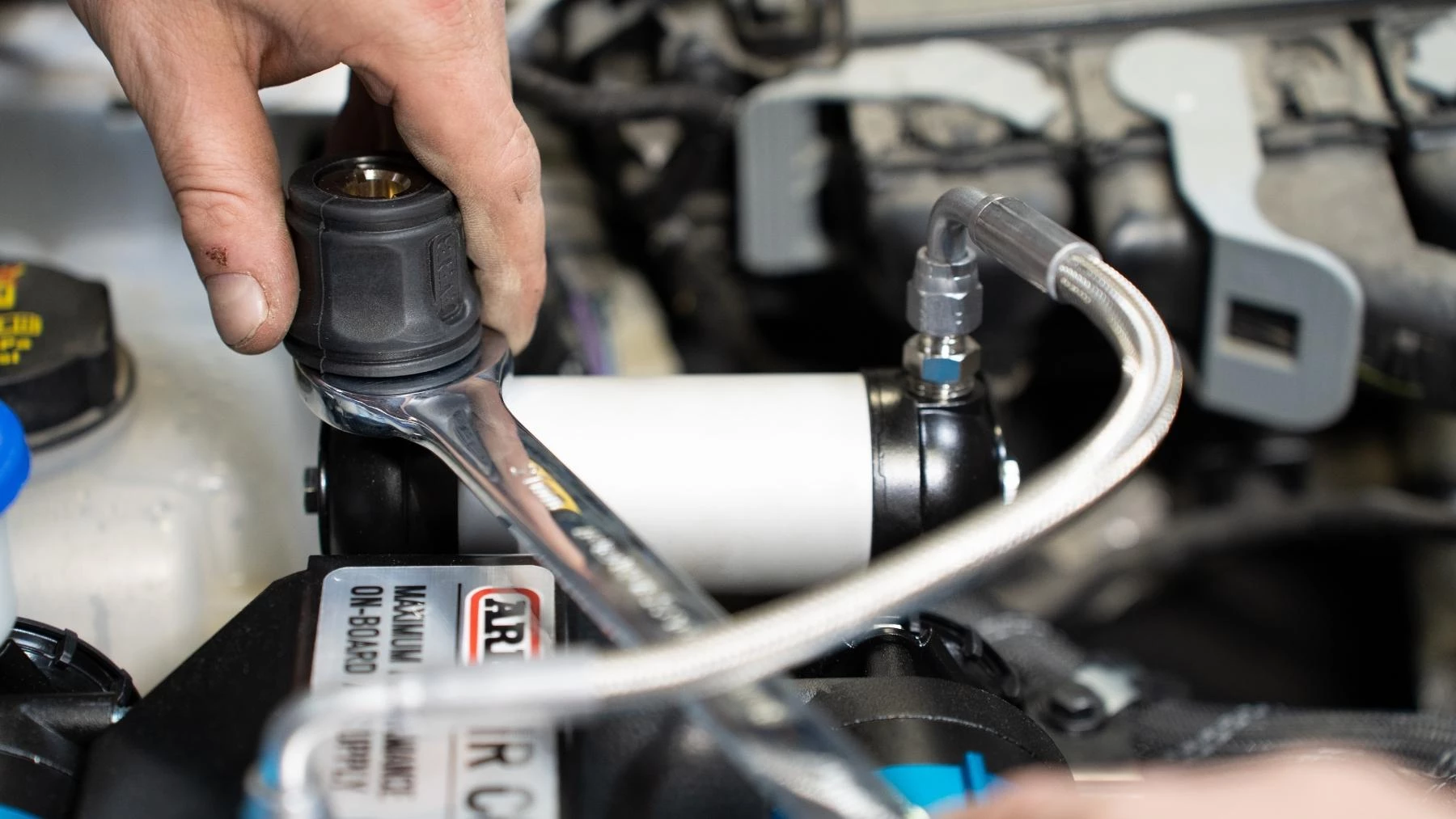
33. Attach the hose coupling (0740112) to the outboard port on the manifold.
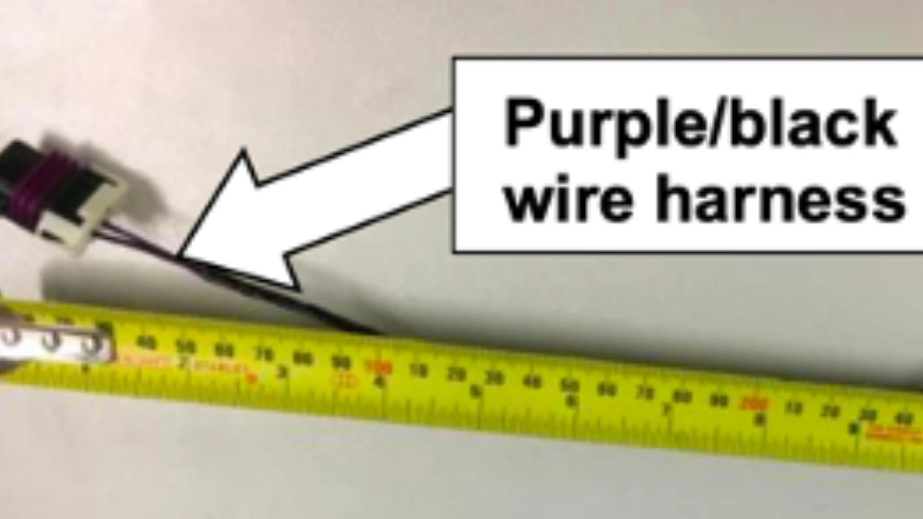
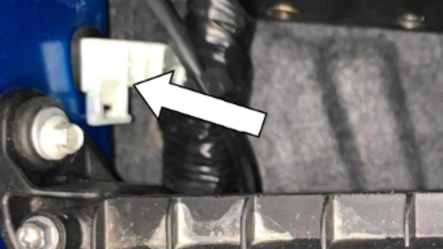
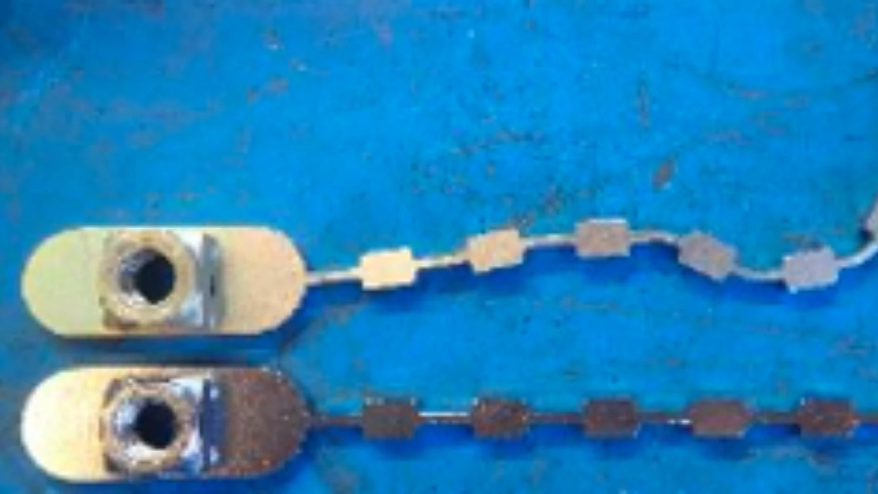
34. Using the wiring harness 180415, measure and cut 400mm of wire (purple/black) connected to the purple plug.
Note: Ensure the plug is retained (as shown above)
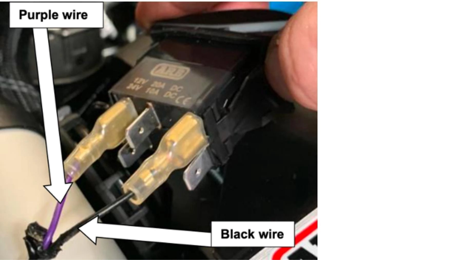
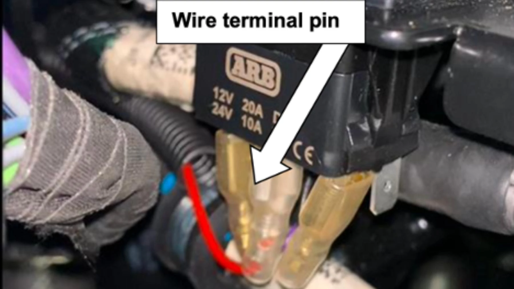
35. Connect spade connectors to the cut ends.
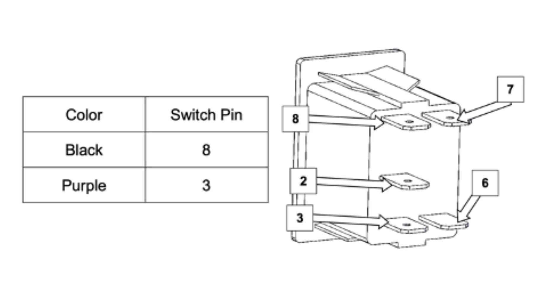
36. Connect spade connectors to the switch as followed:
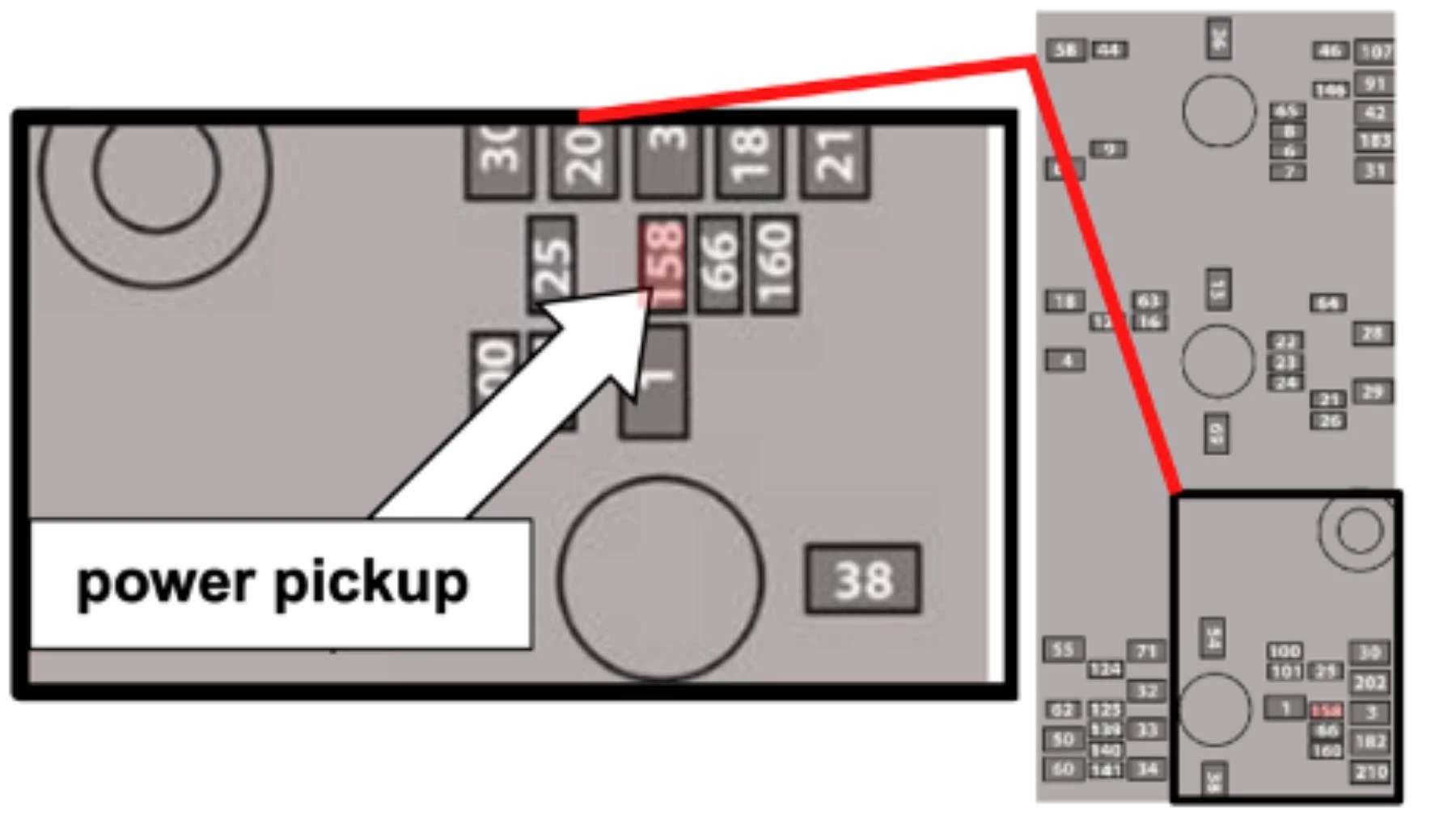
37. Pickup power from the stability bar module fuse (10A) located in the engine bay fuse box. Fuse reference #158 in the owner’s manual.
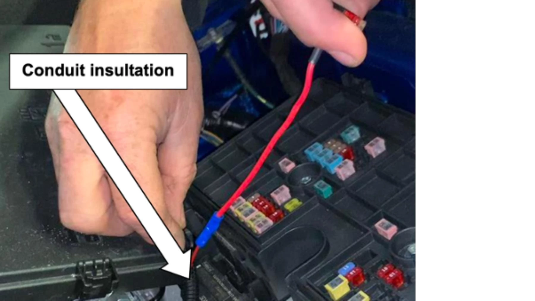
38. Run wiring around the rear section of the engine bay to the compressor switch.
Note: Ensure to insulate the wiring in the conduit.
39. Connect spade connectors to switch pin 2.
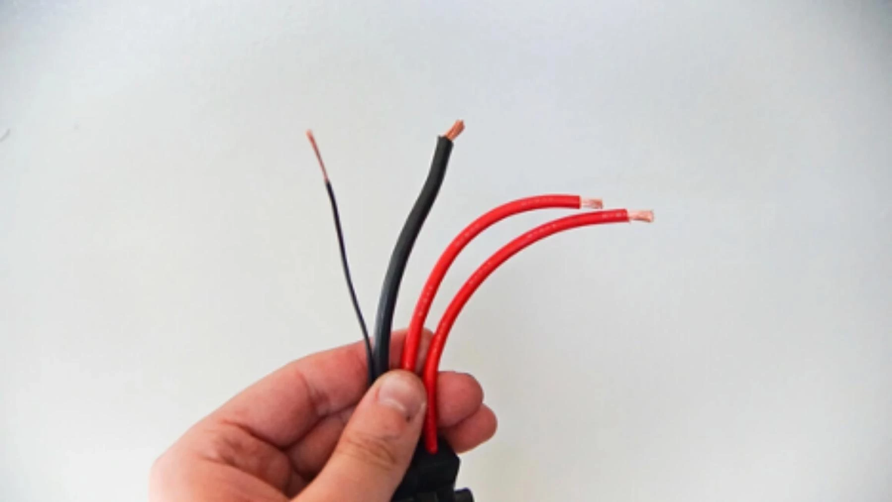
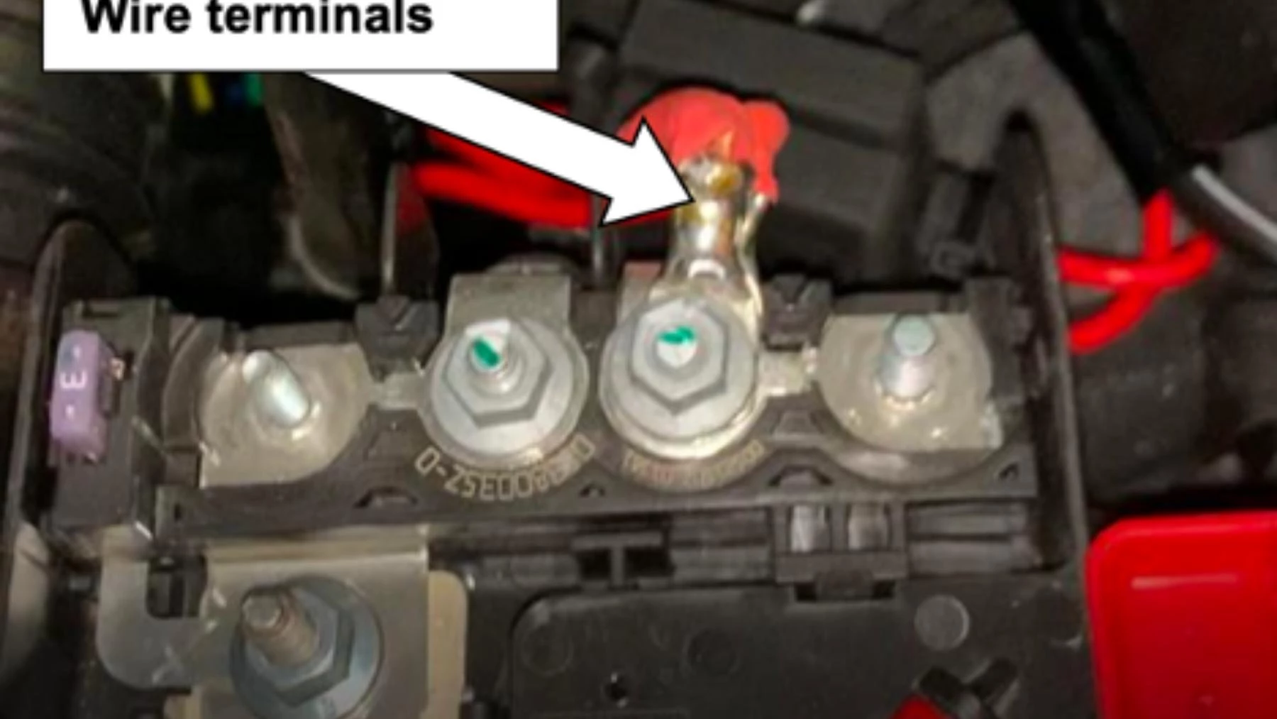
40. Crimp a terminal to the end of each of the two red wires on the compressor wiring harness (pn. 180414), and then connect to the positive battery terminal.
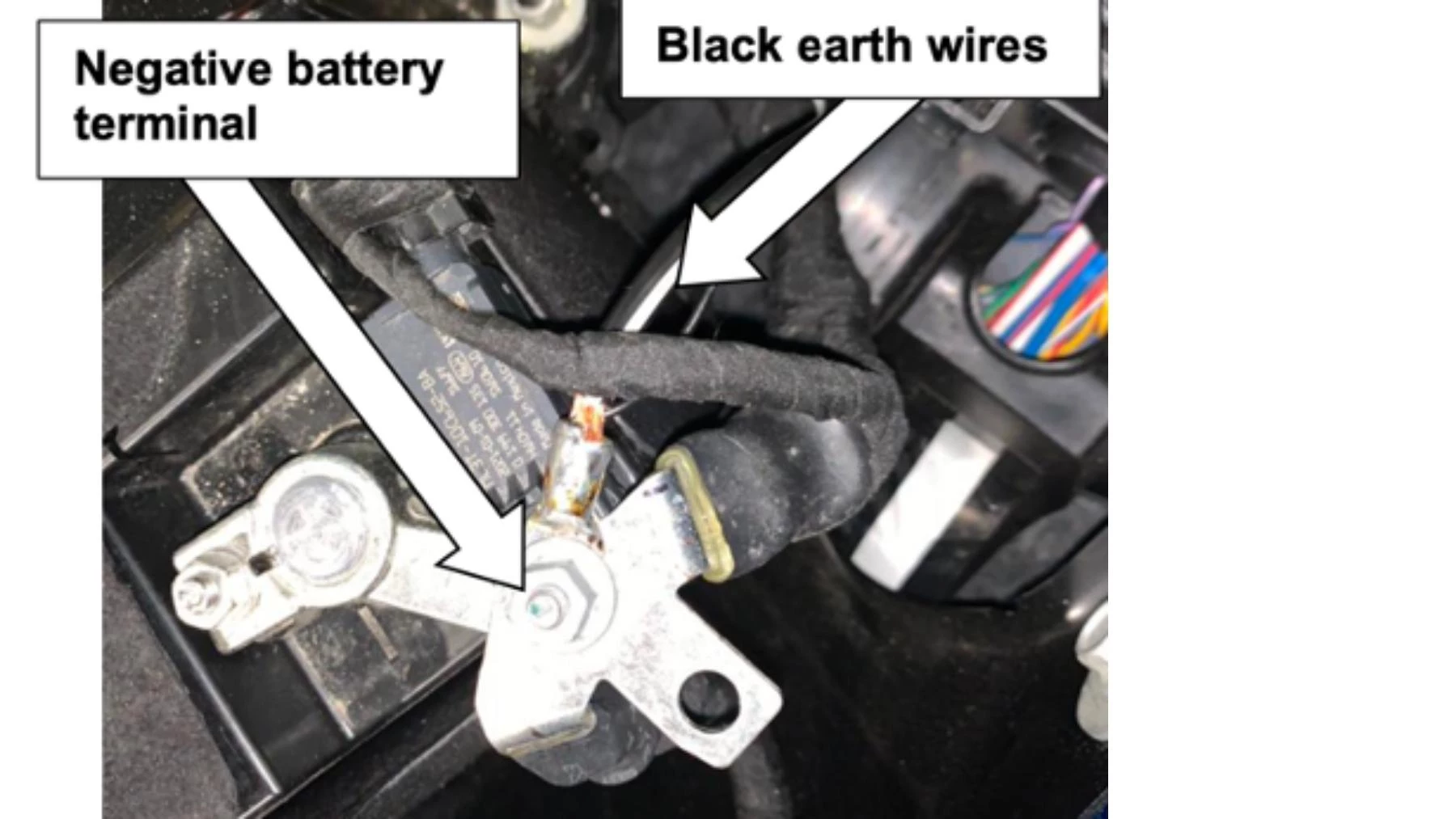
41. Connect the 2 black earth wires from the compressor wiring harness to the negative battery terminal.
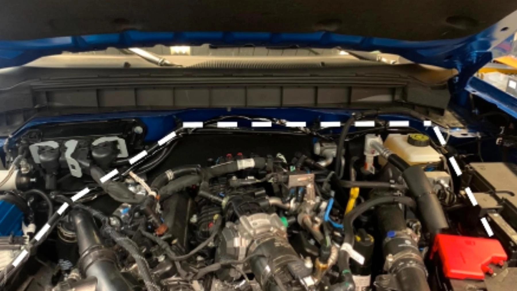
42. Route the harness around the back of the engine bay. Cable tie every 400mm.
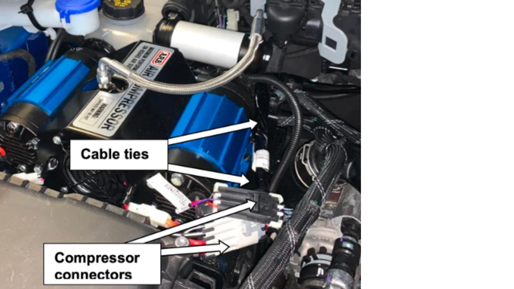
43. Plug the two harnesses into the compressor connectors.
44. Cable tie the harness to the base plate.
Suits 2.3L & 2.7L Ford Broncos - Not compatible with Bronco Raptor and Everglades models
Up Next:
How to Choose an Old Man Emu Suspension System
Old Man Emu suspension prioritizes ride quality and control while accounting for driving style, terrain...